The efficiency of the buck converters work better when there is some spread between input voltage and output voltage.
Converting 7.4V to 5V is less efficient that converting 10.4V to 5VDC for a buck converter.
Does that sound correct?
Not to me. I don't wanna give a lecture in power electronics, but I built the one or the other buck converter myself. I also worked as a development engineer for lithium battery packs. I had this kind of discussion almost once a week

Normally a buck converter's efficiency is best when V_in = V_out, which of course is only the case for a short term certain situation but not the normal case (otherwise you wouldn't need one), 'cause in this special case there is only the internal resistance of the full conducting switch (MOSFET), and maybe a current measuring shunt. Its efficiency drops the larger the input voltage differs from the output voltage. And step-up (V_in < V_out) is always worse than step-down (V_in > V_out).
You know the squarewaves of a PWM:
Now you need to imagine the square's edges are not infinite steep but slightly skew. The off-to-on, and turn-off steps not happen immediately but need time; short, but not zero. Depending on the FET some femto- or pico- (e.g. CPU-internal), or nano- to microseconds, as more common in such cases. So in every full switch-on and full switch-off cycle the FET's conducting layer is completely driven through all stages of partial conductance from open (max. resistance; about some MOhm) to closed (full conduction; about a few Ohm down to milliohms for the better ones), within this FET's typical (datasheet) unchangeable amount of time.
So if you reduce the pulse width, which you more need to do the higher V_in is to V_out, the more part of rate the partially conducting stages become of the squares, thus lowering efficiency.
So for not getting more deeper: In this case two cells serial were better than three, yes.
I don't think efficiency is a concern.
Depends on how much you care about your battery's life.
Which means one of two things:
a) the capacity, which is the amount of energy can be used between two recharges.
b) how many recharge-use-cycles your battery will live until its capacity left is reduced that much you decide it's not usable anymore. batteries age, which means they lose capacity over time, which means both more charge energy is needed (more time with the same charging current) to get the battery fully charged, while less energy is available, the battery is quicker depleted when it's discharged (used).
The importance of converters in any battery powered system are often underestimated if not completely overseen, but they are a crucial part of it.
There are two points of a converter concern this:
1. Its efficiency, which effects a)
2. Its retroaction on the battery cells, which may effect b)
Efficiency is crucial about your battery's life. You don't need to do math to see:
If your converter has an efficieny of 50% it means your device will only see 50% of the battery's capacity.
Example: You device needs constantly 500mA, and shall be used for 4 hours. So you estimate 2Ah for your battery's capacity, right? Well, if your converter has 100% efficiency, so does not come from this universe. If it has 50% you better chose 4Ah, because the "rest" is transformed into heat - wasted by the converter.
Typical rule-of-thumb efficiency values for converters are:
<35% is crap, but not seldom
~50...70% is okay, and common
~75...90% is good, but not regular
>90% is top, very rare, often expensive, mostly for larger system as what we're talking here, and mostly individually tailored (built by yourself
)
(see datasheets for exact details of a certain part for certain voltage levels [and don't you trust everything you read in datasheets always blindely. if you need to rely on the values, measure yourself])
For the second point you need to imagine the square wave again, and see in reality there are over- and undershoots at the square's edges:
green is the ideal (theoretical) square wave, blue and red are like real signals look. blue without filtering (or buffering) the over- and undershoots.
They are inevitably. Their origin comes from the capacity within the FET's layers, and happen every time the FET switches, and became the larger the faster the FET switches (there are other, additional influences, but I want to keep it simple and useful for this case.)
They can be involunterely increased by additional inductive and capicitive attributes other parts bring, such as wires (inductive), motors (also L) and their input capacitors are most common sources. You get a R-L-C oscillation circuit, if you are aware of it, or not. If you're not aware of it, not measuring, it can happen you hit by accident parameters very good for oscillation, maybe even near resonant frequency...

!
Within a 14.4V power tool (an ordinary, common screwdriver) in the lab I once measured a >200A(!) peak (

); it was only for one and a half microseconds, so nothing you need to be concerned about wires getting warm, but it was there.
And that's where it can be an issue for your battery cells:
If not known/avoided/damped those peaks can easily overshoot the square wave's rated values by >100%. They come with each and every square of the converter's PWM. If your converter is running at say 100kHz, or even more (the 'small ones' can run at MHz frequencies), you can imagine this as kind of a very tiny machine gun, but firing constantly at your cells with hundred thousand rounds per second, thus lowering life time.
So, measure. And if they are a concern (do you stay within battery cell's specs, or do they overshoot significantly?), filter them, or try another converter.
But the most important concern
teekay already mentioned:
At around 6.5V there should anyway be a low voltage cut-off to save your batteries.
You must not overcharge nor overdischarge battery cells.
That's the quickest way to kill a battery besides to hit them with a 10kg hammer.
In your cell's datasheet you'll find the two values for max allowed charging voltage (4.2 ... 4.5V), and the lowest allowed voltage while discharging: (2.5 ... 3.4V)
You need to ensure your device/application/converter/whatever measures constantly those two voltages, and stop charging/discharging in time, or cut off the battery if those limits are exceeded.
Within commercial battery packs there are safety circuits (that's what I used to design most back when I was in battery business); within commercial products they are mandatory, otherwise it's a violation of UN regulations.
If your converter does not come with such a input voltage control you may do it yourself by simply comparing two reference voltages with the cell's voltages, and switch off a FET when the limits are exceeded (a most simple OpAmp/comparator circuit.)
But watch out to build this circuit as low consuming as possible. Otherwise this one sucks your battery dry in no time, and may become itself a cause for heavy discharge of your battery (I've seen so much crap, it hurts!

)
Of course, if you don't care if your device works for 20 hours or only 3, and your battery lives for five years, or just a half, and it's for personal use only, you don't need to become scientific about it.
But you asked, and I told what you need to watch out for if it shall be engineered.

Edit beancounting:
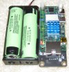
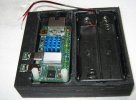
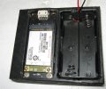
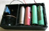
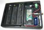
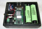
Those cells your picture shows are LiIon, not LiPo.
LiPos come as pouch cells:
typical example of a single cell LiPo package containing a safety circuit (under the yellow tape)


 Damned! That's the 30Ah of the battery's capacity!)


")
