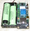
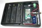
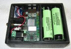
Powering a Rock Zero 3E with Li-Ion batteries...

I am looking for some input on what to use for battery pack to power Zero 3E at 5VDC.

Lipo Battries run about 3.8V each so two 18650 batteries would give me around 7.4V. I need a buck regulator for 5V.

From what I understand I might be better going with three batteries for 10.4V.

The efficiency of the buck converters work better when there is some spread between input voltage and output voltage.
Converting 7.4V to 5V is less efficient that converting 10.4V to 5VDC for a buck converter.

Does that sound correct?
 
I am using Raxda Rock Zero 3E and I have attached an MiniPCIe adapter to the bottom. I used a Sierra 4G Modem mainly for the GPS.
Looking to power a Cellular Modem with FreeBSD using batteries.

I am using this for my Voltage Converter:
 

Attachments

  • zero3E.JPG
    zero3E.JPG
    509.8 KB · Views: 257
I think two batteries should be fine, I don't think efficiency is a concern. The worst case is when your batteries are low, i.e. around 3V each, meaning it's outputting 6V, so there's only a 1V headroom for the buck converter, but I've run a Pi 4 like this and it has not been a problem. At around 6.5V there should anyway be a low voltage cut-off to save your batteries.
 
The efficiency of the buck converters work better when there is some spread between input voltage and output voltage.
Converting 7.4V to 5V is less efficient that converting 10.4V to 5VDC for a buck converter.

Does that sound correct?

Not to me. I don't wanna give a lecture in power electronics, but I built the one or the other buck converter myself. I also worked as a development engineer for lithium battery packs. I had this kind of discussion almost once a week :cool:

Normally a buck converter's efficiency is best when V_in = V_out, which of course is only the case for a short term certain situation but not the normal case (otherwise you wouldn't need one), 'cause in this special case there is only the internal resistance of the full conducting switch (MOSFET), and maybe a current measuring shunt. Its efficiency drops the larger the input voltage differs from the output voltage. And step-up (V_in < V_out) is always worse than step-down (V_in > V_out).
You know the squarewaves of a PWM:
1745655482694.png

Now you need to imagine the square's edges are not infinite steep but slightly skew. The off-to-on, and turn-off steps not happen immediately but need time; short, but not zero. Depending on the FET some femto- or pico- (e.g. CPU-internal), or nano- to microseconds, as more common in such cases. So in every full switch-on and full switch-off cycle the FET's conducting layer is completely driven through all stages of partial conductance from open (max. resistance; about some MOhm) to closed (full conduction; about a few Ohm down to milliohms for the better ones), within this FET's typical (datasheet) unchangeable amount of time.
So if you reduce the pulse width, which you more need to do the higher V_in is to V_out, the more part of rate the partially conducting stages become of the squares, thus lowering efficiency.

So for not getting more deeper: In this case two cells serial were better than three, yes.

I don't think efficiency is a concern.
Depends on how much you care about your battery's life.
Which means one of two things:
a) the capacity, which is the amount of energy can be used between two recharges.
b) how many recharge-use-cycles your battery will live until its capacity left is reduced that much you decide it's not usable anymore. batteries age, which means they lose capacity over time, which means both more charge energy is needed (more time with the same charging current) to get the battery fully charged, while less energy is available, the battery is quicker depleted when it's discharged (used).

The importance of converters in any battery powered system are often underestimated if not completely overseen, but they are a crucial part of it.
There are two points of a converter concern this:
1. Its efficiency, which effects a)
2. Its retroaction on the battery cells, which may effect b)

Efficiency is crucial about your battery's life. You don't need to do math to see:
If your converter has an efficieny of 50% it means your device will only see 50% of the battery's capacity.
Example: You device needs constantly 500mA, and shall be used for 4 hours. So you estimate 2Ah for your battery's capacity, right? Well, if your converter has 100% efficiency, so does not come from this universe. If it has 50% you better chose 4Ah, because the "rest" is transformed into heat - wasted by the converter.
Typical rule-of-thumb efficiency values for converters are:
<35% is crap, but not seldom
~50...70% is okay, and common
~75...90% is good, but not regular
>90% is top, very rare, often expensive, mostly for larger system as what we're talking here, and mostly individually tailored (built by yourself :cool:)

(see datasheets for exact details of a certain part for certain voltage levels [and don't you trust everything you read in datasheets always blindely. if you need to rely on the values, measure yourself])

For the second point you need to imagine the square wave again, and see in reality there are over- and undershoots at the square's edges:
1745658650191.png

green is the ideal (theoretical) square wave, blue and red are like real signals look. blue without filtering (or buffering) the over- and undershoots.

They are inevitably. Their origin comes from the capacity within the FET's layers, and happen every time the FET switches, and became the larger the faster the FET switches (there are other, additional influences, but I want to keep it simple and useful for this case.)
They can be involunterely increased by additional inductive and capicitive attributes other parts bring, such as wires (inductive), motors (also L) and their input capacitors are most common sources. You get a R-L-C oscillation circuit, if you are aware of it, or not. If you're not aware of it, not measuring, it can happen you hit by accident parameters very good for oscillation, maybe even near resonant frequency...💩!
Within a 14.4V power tool (an ordinary, common screwdriver) in the lab I once measured a >200A(!) peak (😲); it was only for one and a half microseconds, so nothing you need to be concerned about wires getting warm, but it was there.
And that's where it can be an issue for your battery cells:
If not known/avoided/damped those peaks can easily overshoot the square wave's rated values by >100%. They come with each and every square of the converter's PWM. If your converter is running at say 100kHz, or even more (the 'small ones' can run at MHz frequencies), you can imagine this as kind of a very tiny machine gun, but firing constantly at your cells with hundred thousand rounds per second, thus lowering life time.
So, measure. And if they are a concern (do you stay within battery cell's specs, or do they overshoot significantly?), filter them, or try another converter.

But the most important concern teekay already mentioned:
At around 6.5V there should anyway be a low voltage cut-off to save your batteries.

You must not overcharge nor overdischarge battery cells.
That's the quickest way to kill a battery besides to hit them with a 10kg hammer.

In your cell's datasheet you'll find the two values for max allowed charging voltage (4.2 ... 4.5V), and the lowest allowed voltage while discharging: (2.5 ... 3.4V)
You need to ensure your device/application/converter/whatever measures constantly those two voltages, and stop charging/discharging in time, or cut off the battery if those limits are exceeded.

Within commercial battery packs there are safety circuits (that's what I used to design most back when I was in battery business); within commercial products they are mandatory, otherwise it's a violation of UN regulations.
If your converter does not come with such a input voltage control you may do it yourself by simply comparing two reference voltages with the cell's voltages, and switch off a FET when the limits are exceeded (a most simple OpAmp/comparator circuit.)
But watch out to build this circuit as low consuming as possible. Otherwise this one sucks your battery dry in no time, and may become itself a cause for heavy discharge of your battery (I've seen so much crap, it hurts!🤪)

Of course, if you don't care if your device works for 20 hours or only 3, and your battery lives for five years, or just a half, and it's for personal use only, you don't need to become scientific about it.
But you asked, and I told what you need to watch out for if it shall be engineered. 🤓

Edit beancounting:
Those cells your picture shows are LiIon, not LiPo.
LiPos come as pouch cells:

1745665102387.png

typical example of a single cell LiPo package containing a safety circuit (under the yellow tape)
 
This may sound silly but just how bad a loss would I have if I just used a Schottky diode inline? Major?

I was playing with those and a 12V SLA Battery. Stung together 3 diodes to get 5VDC.

The reasoning is simplicity. Good learning as well.

Back to your original point heat = waste and with a Diode I would expect heat. Simplicity is a goal here..

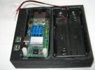
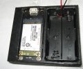
I did a mockup this morning. I have to do some notching for SMA antenna jack and power/usb-C solder adapters.
 

Attachments

  • fitup.JPG
    fitup.JPG
    1.3 MB · Views: 238
I was trying to decide which way works best. Upside down is probably not best. Zero side up for ease. I started a three Li-Ion Battery version too.
I might do a stacker version so better access on one side battery and other Zero3E.
 

Attachments

  • gps.JPG
    gps.JPG
    1.4 MB · Views: 213
At around 6.5V there should anyway be a low voltage cut-off to save your batteries.
I was kinda ignoring this factoid.

It really looks like I should use a Battery Management Controller too. I messed with a Ti i2c one so I know a little.

I corrected the title to reflect my actual battery type.
 
It makes me twitch seeing people assume a LiIon battery is 3.7V, they need to appreciate the difference between nominal and maximum.
 
Well the 18650 leave the charger at 4.2VDC but I have to have some way to regulate them so I will use the Mini360 buck I linked to.

I bet I could do a 3P battery setup and the board wouldn't complain. The USB connection would be unhappy though.

I soldered together a bunch of different TTL GPS modules but I decided to start at USB GPS. Messing with DT Overlays for adding another UART is messy.
 
Looking at the Panasonic NCR18650B datasheet they call nominal 3.6V and maximum 4.20V cutoff. Low battery cutoff protection at 2.7VDC
 
how bad a loss would I have if I just used a Schottky diode inline? Major?
Could be, yes.
A Schottky can be a counter measure to protect the battery cells from converter's PWM peaks, yes.
But just because there are ineviteable peaks doesn't neccessarily mean they are destructive, and counter measures are needed. First measure if the overshoots are that large so there is really a need for counter measures, or if you can live without any, which was best of course.

Any additional part within the power line means additional resistance, so energy loss, so efficiency reduction. Also the forward conductance of a very good diode is not zero (depending of the type a diode produces a voltage drop of 0.2 ... 0.6V which for low voltage app is a lot - too much.) Plus: even fastest Schottkys have response times, so they do not block everything.

Best way was - if you measured critical overshoots - to see what you can do by changing the length and form of wires, maybe adding a small capacitor, sometimes (seldom) even a small inductor may help.
In many cases this is quite enough. If not, try another converter (frequency).
If those are not helping, and your powerline still rings too much, then you look for further measures.

It's always a trade off what to prefer on which cost. It all depends on your application's target. Do you need to have one battery's charge last as long as possible, or do you need to replace the battery pack as seldom as possible? It may, or may not make sense to save 40% battery pack's life time for the cost of 20% capacity.
You may also come back to your 3 serial cells idea. This way you lower the efficiency of your converter, but increase battery pack's life time, because this way the cells are stressed less for the same job, plus you gain 50% more capacity (and 50% more weight, needed space, and cost... - it's all a trade off)

This I can only answer vaguely in general. Of course for getting detailed answers you need to specify what you need more precisely, look at what exact values each module has, measure, and do calculation to find the combination which offers you the best trade.
 
Looking at the Panasonic NCR18650B datasheet they call nominal 3.6V and maximum 4.20V cutoff. Low battery cutoff protection at 2.7VDC
'nominal' is for marketing, for the bucket - of no interest for engineering 😁
The other values are the absolute max limits. In this case the protection circuit should be set to 4.25V and 2.65V, but only if the protection circuit is used as one, and not as the standard switch you ran into every time you charge/discharge the pack (yes, I've seen lots of crap!) but let it be correctly done by the charger, and your device switching off in time, which limits best was chosen to not charge above 4.1V, and not to discharge below 2.8V for normal duty (as with this Panasonic cell as example). (I've used some battery's engineer experience into this, not elaborating it, but to give some practical values that way your battery will live longest.)
 
After reading the datasheet I don't think I need a BMC with these removable 18650 batteries. They have cutout protection.
But back to spread. 2.7v+2.7v means my batteries will not cut out until ~5.4v. That will not be enough to drive 5V output buck. So I will need to do some testing.

I bought a case of these batteries from a genuine source sealed about 5 years ago.

So these are somewhat disposable to me. I have only used a handful and they will become obsolete if I don't use them.

I also have a bunch of old laptop cells I salvaged the good ones. Those are unprotected and flattops..
 
They have cutout protection.
All cylindric LiIon cells (18650, 26650) have an internal protection, which cuts off the plus pole cap from the electrode. When the cell is overcharged too much (>4.5V), besides gas elementary lithium is procuded in the cell. This measure prevents the housing from burst open by overpressure and the lithium from having contact with air's oxygen, which - you guessed right - will result in fire (metal burning >2000°C! [Never ever use water to try to extinguish a burning battery pack - you additionally cause a hydrogen explosion! Have a sand bucket by hand, or a special extinguisher for metal burn.])
But this is a worst case saftey measure, the last straw, no replacement for a safety circuit, which is also no excuse for not having the charger and the application stay within the limits.
 
After reading the datasheet I don't think I need a BMC with these removable 18650 batteries. They have cutout protection.
But back to spread. 2.7v+2.7v means my batteries will not cut out until ~5.4v. That will not be enough to drive 5V output buck. So I will need to do some testing.

I bought a case of these batteries from a genuine source sealed about 5 years ago.

So these are somewhat disposable to me. I have only used a handful and they will become obsolete if I don't use them.

I also have a bunch of old laptop cells I salvaged the good ones. Those are unprotected and flattops..

The 2.7V is a worst-case, you shouldn't need to take it below 3.4V or so, because beyond that the voltage falls rapidly. You aren't loosing much capacity by shutting off at 3.4V, but you gain a lot of safety and cycle life for you batteries.
 
I need to come up with some protected power splitter like this but mini:

I would like to tie 'shore power' into my rig without worrying about blowing up the batteries with backfeed.

The Mini560 has dual inputs but I know better...
 
and noticed it used zero amps with no load.
Can be. Cannot be.
Depending on how and where you measure those zero Amps doesn't neccessarily mean 0.00 mA are drawn from the battery 🥸
Just for when designing battery devices in general:
If your device is recharged regulary, and your battery has enough capacity, it may of no concern.

Example: Your device is continuously running, e.g. solar powered, so recharged every daylight. The solar panel is large enough to fully recharge an almost depleted battery within 3 hours while you battery's capacity stores enough to keep your device running for four days anyway. So more than enough reserve. roughly check and estimate the values and you're good to go.

Example 2: A battery powered device staying long periods in storage, e.g. a golf trolley. Typical trap: The developers see their trolley uses 3...6A in operation and is used for 4..5h on 18 holes, so they estimate 30Ah for the battery's capacity. Which is the first trap: They use the rated capacity as the battery pack's nominal capacity, so don't factor in the battery ages, which will result in the next season the battery may last for a bit more than 17 holes. But within the first season everything is nice. customers, designers, sellers - everbody's happy.
The season ends. The trolley goes into the barn for winter storage. Next spring it shall be awaken from hibernation, but it's dead as a stone. Not even the slightest flicker of a LED. Nothing. Dead. A measurement reveals cell's voltages <1.8V. Deep Overdischarge. Battery killed.
Turns out: The designers knew their electronics - motor's drive control in stand-by, switch-on button, fuel-gauge, [bad designed] protection circuit - draw 10mA constantly from the battery even if the trolley is not used in stand-by. They said: 'Dude, what are lousy 10mA in comparison to 6A? Negligibly. Nothing!'
Well, not when the device is in operation, sure. But when it stays in the barn for four months, you do
%bc
10*24*30*4
28800

(😨 Damned! That's the 30Ah of the battery's capacity!)
Yep. The "rest" is: Of course the customer does not fully recharge the battery before the trolley goes into hibernation. And of course the battery is not unplugged even if it's mentioned so in the handbook.

So bottom line:
Battery design errors are the sneaky bitches kind of traps. Everything looks perfect at the start. They're revealed many months later, when you forgot all about it.
So measure. directly at your battery's cells package (even before the protection circuit.)
Search for milliamps! 🔍
 
I have been pecking away at this project. I have a working prototype with two 18650 booting up and I have two more in various stages.
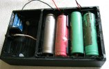
Good advice to just test things. I made a 2S, 3S and 2S2P versions to check runtime. I decided on 2S2P to facilitate battery changeout without external power needed.
 

Attachments

  • IMG_0371.JPG
    IMG_0371.JPG
    1.4 MB · Views: 213
  • IMG_0370.JPG
    IMG_0370.JPG
    1.8 MB · Views: 204
  • IMG_0379.JPG
    IMG_0379.JPG
    1.6 MB · Views: 200
draw 10mA constantly from the battery
I am faced with a 10mA difference in two USB GPS modules.

One draws 90mA and one draws 100mA. Ublox draws more even though it has internal UART. Other module is GPS behind FTDI UART yet it only draws 90mA.

This is all according to usbconfig output. How reliable are these numbers? They never seem to fluctuate? Is this just an initial power draw figure?
What is usbconfig using for power numbers?

I will manually test them to see how they stack up. See if usbconfig numbers are usable. 10mA could be alot on battery power.

Can I get any recommendations for measuring power via chip like INA260 via GPIO. Do we have any power monitoring chip drivers? i2c would be ideal.
I want to monitor voltage and have the machine shutdown at certain threshold.
 
Just as an additional tip for the battery (if not already done):
Those measurement devices (at a glimpse glance the first one looks convincing to me) will be of good use, and will reveal interesting facts, helping you on a solid design a lot in any case. No question.
But to get a value what's actually drawn from your battery, simply attach an amperemeter directly at it.
Most of the times there are two wires (mostly red and black), coming from the cells to a connector's plug. Cut one (or both, if you want to test the precision of two amperemeters), and let the current flow directly through one of your better lab's amperemeters.
This way you get a trustworthy value as the gross sum which current is drawn from the battery in every situation, such as full or partial load of different modules, stand-by, or hibernation.
You could also use a shunt resistor, attach your oscilloscope, and see if there are peaks.
 
FWIW, these days I prefer ADC-s with a built-in voltage reference.
Such as, for instance, ADS1115.
Relying on Vcc being known and stable is too unreliable ;)
 
V_cc is commonly known as the IC's positive supply voltage pin, so equal to the board's supply voltage, which is never a good choice as reference for neither measurement task.
Depending on the DC/DC converter itself (LDO mostly) that provides the voltage, its production tolerances, its input voltage, the current load situation, and other factors like temperature, the supply voltage may not only has an offset from its rated voltage by +/-10%...20% (not seldom even more), may vary because of load changes and temperature, but is also relatively noisy (especially when switching is somewhere onboard, like any kind of digital signal lines, processors/controllers, or buck converters.)

For any ADC you always need a precise and stable reference voltage. Otherwise you're producing more kind of random values but nothing could be named 'measuring'.
Some ADCs come with an internal reference voltage, others don't. The internal ones are in most cases something like 'above medium good'; suitable for most common measurement tasks (see according datasheets for details of specific ICs.)
If you need more precision you chose an external voltage reference (Many ADC ICs with internal V_ref can be switched to external sources.)
Among those reference voltage ICs you'll find pretty precise ones (<0.5...0.1%), temperature stabilized etc.
 
Please excuse my crude circuit. I plan on adding enhancements from here.
Number one on list is mini-slider switch on battery side. Hard wiring it was not smart.
Battery protection circuit or BMS possible. Still reading.

So I have a question. I really like the ina3221 chip. It is well suited for a bigger project like monitoring APU2 but we have no driver for it.

Q: Device Tree Bindings allow some Linux drivers to be imported while compiling ARM DTB files. Would this make them usable on FreeBSD ARM or is there still a FreeBSD kernel driver required?
 
Back
Top