The Robot Thread

Another clone of?? Matek which SpeedyBee cloned. They are now called CoreWing ?? How do you keep up.
yes, there are a lot of clones, that's why I don't panic when I see a board and it's not in the ardupilot list. We have a joke "there is wine in the bottles, there are no labels" :)

Those XT60 and XT90 need some heat.
you need a soldering iron of at least 60 watts, a regular copper one will also work
 
Maybe I could use SDR for Video Ground Station/VTR. That would be ideal for me.

 
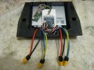
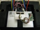
Today I finished a chassis for Two ESC and Flight Computer for my Rover. This brain box fits in the original controller location.
Mounted the flight computer on small tab. Found out Matek uses slightly different bolt hole pattern than the Sologood Wing.
I am using a UART GPS module but without SDA/SCL Compass. What am I missing without compass on ROVER?

I am still having trouble figuring out why you cannot drive R/C Signal Wire to ESC with ARM64 GPIO PWM pins.
 

Attachments

  • brain2.JPG
    brain2.JPG
    1 MB · Views: 30
  • brain1.JPG
    brain1.JPG
    828.7 KB · Views: 37
Thanks You I will order an M10 module today. I didn't realize it was so integral.

Had this smell of white smoke in my lab. Killed all house breakers and still smelled it.
Turns out my 3 Pack holder for 18650 had all the wires bare and was smouldering.
Looks like a wire on bottom joining poles must have grounded on something when I laid it down after work..
They are very cheaply made 18650 holders I bought. I was thinking the wires seemed mighty thin for 3 cells.

Kids don't let kids use LiPo indoors.
 
I mounted my flight controller at a weird angle because I want the "Heads Up Display" onscreen display to work without adjustments.

My Rovers previous controller bracket was at a 30 degree angle so I designed around that requirement. Flight controller mounted @30 degrees. So nap of earth should be correct.
 
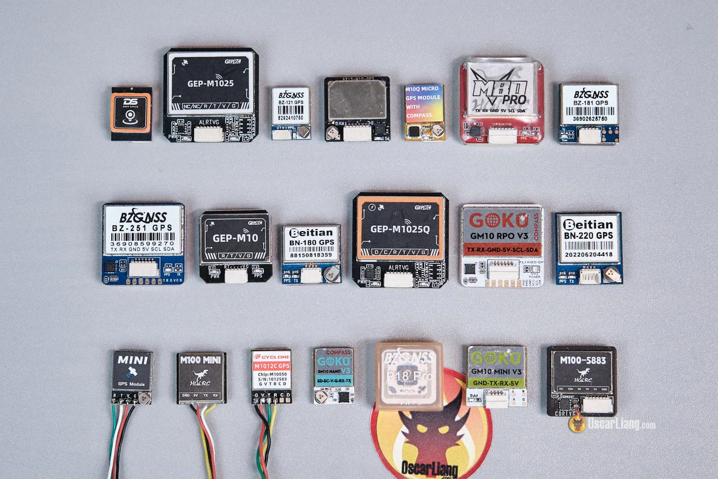
I really did not put enough research into GNSS + Compass.

Oscar has a good review.

But I am different. I want external GPS antenna. My rovers electronics are close to ground. I want antenna on a mast.
So none of the above GPS+Compass have U.FL(IPEX) connectors for antenna pigtail. Turns out they are not very common.
Fly guys don't need to worry about GPS reception as much as ground vehicles do.

External Antenna module I am considering:
Cheap enough but my whole endevour depends on locational awareness. Two tires driving and steering.

So I see ZED-F9P and research RTK. Great stuff. Centimeter accuracy possible. But No Compass Module. Found a few options:
MicoAir MG-F10
Ticks all boxes. External Antenna, Newer Ublox Module, Dual Band. ~$70
Not RTK but I see no RTK modules with Compass. I don't need RTCM server of RTK.
I was thinking of using ZED module for backup GPS. That would not require compass.
 
OK resora I have some technical questions for you.

I see that I can hook up my R/C Controller and Receiver to my Wing Flight Controller.

So I would plug in the SBUS lines on Flight Controller to the "Bat/Tele" pins?


My R/C controller:

Is this gear too old to use for Rover Manual Controller?

During mission operation I could walk along side of Rover and take over manual control then resume path?
 
So I would plug in the SBUS lines on Flight Controller to the "Bat/Tele" pins?
wrong, sr 300/3000 operate via Spektrum’s DSM System protocol, not via SBUS
During mission operation I could walk along side of Rover and take over manual control then resume path?
ardupilot allows you to switch between manual control and mission planning
Is this gear too old to use for Rover Manual Controller?
It will work for rover functions, there are a few drawbacks, for the device, only two channels, but for the rover it will work, but remember what board you have to check if it supports Spektrum's DSM, you may need to switch to equipment that supports SBUS, ELRS, CRSF
 
Thanks so much for the assistance.
Going off your help I found ArduPilot help pages. I had no idea DSM was they keyword I needed to look for..
And I see here it is mostly PixHawk that has DSM Pins. I have not seen them on any F405Wing. Will doublecheck.
I thought it was too good to be true. The R/C controller pair are probably 15 years old. New never used. Had robot on the mind back then.

I harvested a Brushless Motor from a cordless Ryobi electric lawnmower. 40VDC and feels stout. The bigger 48V motor here looks nice. Almost double stack

Shopping ESC for Brushless I found Alien Power Systems. I really like the products. UK outfit.
I saw a Twin CAR ESC but paused on buying off ebay and it is now gone. $50 for 150A dual signal but maybe older at 8S voltage. New ones are 12S. They look quality.

I see some high end ESC have an STM32 F4 inside....

I might buy a second motor like the one I harvested for some future rover vehicle use. The 48V ryobi ones are going for too much money used. $40 vs. $175

I have worked with stepper motors but not BLDC motors.
 
Looking at the manpage for one of my boards I noticed I do have Serial RC on UART1. So different connector but mght work. Excellent.
DSM/SRXL connects to the RX1 pin, but SBUS would still be connected to SBUS.

VESC is an open source ESC design standard and more..
Interesting ESC with USB interface interface. FlipSky calls their controllers VESC Design.


Video of my motor in action:
View: https://www.youtube.com/watch?v=1GbapecvzQs
 
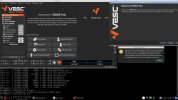
VESC tools build FreeBSD. This is just the beginning, I haven't created the firmware yet, I don't know how the project will go further and whether it is needed.
 

Attachments

  • vesc.jpg
    vesc.jpg
    257.3 KB · Views: 16
Phishfry
I build the firmware from https://github.com/vedderb/bldc
what do you think is the port FreeBSD needed ?

Bash:
   text    data     bss     dec     hex filename
 450968    2804  172308  626080   98da0 /home/res2500/code/bldc/build/flipsky_60/flipsky_60.elf
Creating /home/res2500/code/bldc/build/flipsky_60/flipsky_60.list

Done
gmake[1]: Leaving directory '/home/res2500/code/bldc'
res2500@res:~/code/bldc $ ll build/
total 24
drwxr-xr-x   6 res2500 res2500 -  512  8 серп. 15:30 ./
drwxr-xr-x  23 res2500 res2500 - 1536  8 серп. 14:35 ../
drwxr-xr-x   5 res2500 res2500 -  512  8 серп. 15:27 60/
drwxr-xr-x   5 res2500 res2500 -  512  8 серп. 15:28 75_100/
drwxr-xr-x   5 res2500 res2500 -  512  8 серп. 14:45 basic/
drwxr-xr-x   5 res2500 res2500 -  512  8 серп. 15:31 flipsky_60/
res2500@res:~/code/bldc $ ll build/flipsky_60/
total 17348
drwxr-xr-x  5 res2500 res2500 -     512  8 серп. 15:31 ./
drwxr-xr-x  6 res2500 res2500 -     512  8 серп. 15:30 ../
drwxr-xr-x  2 res2500 res2500 -    5120  8 серп. 15:31 .dep/
-rwxr-xr-x  1 res2500 res2500 -  524280  8 серп. 15:31 flipsky_60.bin*
-rw-r--r--  1 res2500 res2500 -  199891  8 серп. 15:31 flipsky_60.dmp
-rwxr-xr-x  1 res2500 res2500 - 4367188  8 серп. 15:31 flipsky_60.elf*
-rw-r--r--  1 res2500 res2500 - 1276433  8 серп. 15:31 flipsky_60.hex
-rw-r--r--  1 res2500 res2500 - 9087172  8 серп. 15:31 flipsky_60.list
-rw-r--r--  1 res2500 res2500 - 2063070  8 серп. 15:31 flipsky_60.map
drwxr-xr-x  2 res2500 res2500 -    5120  8 серп. 15:31 lst/
drwxr-xr-x  2 res2500 res2500 -    5120  8 серп. 15:31 obj/
 
resora Yes that would be great. So it looks like the firmware is similar to the flight controllers with a bin and hex file.
I am under the assumption that you can monitor the motor via USB connection to the ESC?

Last night I purchased two of the 50A FlipSky controllers.

I also took your advice and bought LiPoFe4 in good sized package. I bought four but may get two more. I am unsure if they will work in series with an internal controller in battery.
At only 5 pounds apiece they are nearly airworthy.
4X the punch over Lead Acid. 4X capacity.
Designed for Harley Davidson use?? I will dog them like a loud ass harley.
 
I am trying to understand motors. I have worked on them for years but was never a consumer.
Trying to figure out what makes a motor "Burn Up" I came across some good reading. Brushed motors the commutator is the weak link.
Brushes are carbon and will wear out. Tearing up commutator. Skimmable in lathe to take the grooves out...

With Brushless motors what is the weak link. When "Overdriving" a Brushless motor you have permanent magnets on the motor casing.
Push a motor too far electrically and you can permanently kill your motors magnets. With mechanical assemblies you have to think of the bearings.
You get a motor too hot and you will fry your sealed roller bearings. Also speed. Motor bearings are designed for a certain speed range.
Overspeeding bearings will kill them. But many bearings you can get different bearings ratings and upgrade a bearing to a higher capacity is possible.
Heat is a limiting factor. Liquid cooling is used in some extremes.

I have ran across something I need to figure out.

The Ryobi 40V mower motors I bought have a very similar motor but in 18V. I bought one of those too to teardown and see what is the difference.
Is it the windings. Is it the Irons Count on Armature. Is it the PM count on the casing?

I took my Ryobo 40V motor and marked a line and counted 16 poles while rotating. So 8 A/B poles I think.
So my first test with the 18V one is check the number of poles. Same frame motor as the 40V one is what is perplexing me.
Maybe they just used different voltages depending on battery packs they were marketing at the time.
Is it actually the same motor but derated by controller used... This was 16" cut versus 20" cut mower.
That is what I am trying to figure out.

I really need to build a torque stand. In combination with VESC software tuning motor controller......
 
I am now shopping connectors for Brushless Motors. For those we have three leads. Choices include MT60 a triangle connector and MR60.
Really not sure if these are heavy duty enough for me. I would prefer a 90AMP connector. There is no MT90 or MR90 connector. 12-14Guage seems to light.
Might be time to solder my own. Never built these. I got some XT60 with 10-Gauge and I really like them. 10gauge seems sufficient. Stout feeling.

Yellow Butt Connectors seem to be a cheap way to connect. They do seem cheezy for the task. I like connectors.
I have the same issue with flight controller. What connector to use. Might just use spade connectors. Seems rudimentary for electronics but it is simple.

I cancelled my order for two FlipSky 50A controller. I need more amps. I bought one Flipsky FESC6.7 70A model instead to test.

Reddit shows me that XT150 bullet connector is a contender.
 
I am under the assumption that you can monitor the motor via USB connection to the ESC?
Yes, theoretically motor control over USB should work. VESC Tool and the BLDC firmware can both be built on FreeBSD. I don't have the hardware to test the complete setup yet, but from the software side everything looks promising.
That sounds like a great setup. I’ve now got the FreeBSD side building both VESC Tool and the BLDC firmware successfully, including several different firmware targets. Once the controllers arrive, we should be able to move from build testing to actual USB communication and motor-control testing.
Those LiFePO4 batteries also sound like a good fit for a rover. I’d just verify with the manufacturer whether their internal BMS supports connecting multiple batteries in series before trying it.
I am trying to understand motors.
This is exactly where VESC should become useful. A torque test stand would let you compare the 18V and 40V Ryobi motors under controlled conditions instead of trying to infer everything from their physical size. Even if they have the same frame and the same number of magnetic poles, the winding could be quite different — number of turns, wire size, Kv/Kt, Om, current capability, and therefore the torque and speed characteristics. With VESC we should eventually be able to control current/RPM and log electrical data while the test stand measures torque and temperature. Then we could build actual torque, power and efficiency curves for both motors. I would be very interested to see whether Ryobi is actually using two different motor windings or essentially the same motor operated at different voltage/current limits by the controller.
I am now shopping connectors for Brushless Motors. For those we have three leads. Choices include MT60 a triangle connector and MR60.
Really not sure if these are heavy duty enough for me. I would prefer a 90AMP connector.
For a 70–90A setup, I would stay with 10 AWG rather than going to 12–14 AWG. Remember that with AWG, a smaller number means a thicker wire.
For the battery connection, XT90 or XT90-S seems like a good choice. For the three motor phases, I would probably use three separate high-current bullet connectors rather than MT60/MR60, especially for a test stand.
One thing we should keep in mind with VESC is that battery current and motor phase current are not the same. The phase current can be considerably higher, especially at lower motor speeds, so I would rather have some margin in the motor wiring and connectors.
From experience, I can say that you can solder such large connectors with a regular "copper soldering iron", but 100 watts

 
Back
Top