Running FreeBSD on Radxa Rock 3C RK3566 board

reading the efi binary from a raw flash partition (where you dd it previously) seems to work
i can get to a loader prompt from spi-nor u-boot

To install this bootloader on an sdcard just do:

dd if=/usr/local/share/u-boot/u-boot-rock-pi-4/idbloader.img of=/path/to/sdcarddevice seek=64 bs=512 conv=sync
dd if=/usr/local/share/u-boot/u-boot-rock-pi-4/u-boot.itb of=/path/to/sdcarddevice seek=16384 bs=512 conv=sync

To install this bootloader on an SPI flash just do:

From my u-boot prompt

=> load mmc 0 ${kernel_addr_r} u-boot-spi.bin
=> sf probe
=> sf update ${kernel_addr_r} 0 ${filesize}

After this u-boot will be written to SPI and will work, when starting it will try to find efi/boot/bootaa64.efi on the efi partition of real OS launch devices,
the polling order is hardcoded in the source code, but it can be changed from the u-boot command line,
after which the settings can be saved in a special SPI flash area.

In my opinion, the polling order is USB/NVMe/eMMC/SD.

This means that if you write my u-boot-spi.bin to SPI flash and previously installed the OS on NVMe
and pulled out the USB flash then u-boot will find an efi partition on NVMe,
run efi/boot/bootaa64.efi(This is loader.efi copy from OS) and you will launch the OS with NVMe directly from ZFS root FS.

This is simple and very reliable and has been working for me for quite a long time on several boards with SPI flash on RK3399.

But Tianocore EDK2 UEFI is even more interesting because it allows you to run GENERIC OS image
in ACPI mode on a new processor even when there are no drivers for the SoC in the OS kernel.

And this is fantastic.

Thanks to this, I am already successfully running FreeBSD 13.2 and 14.0 on many RK3588 boards.
And these are 8 cores and PCI3.0x4 NVMe, 2.5 Gbps Ethernet and HDMI working in frame buffer mode,
for a home server it’s not bad considering that it consumes no more than 25 watts.

Yes, and RAM up to 32GB :cool:
 
when you build u-boot it creates u-boot-rockchip-spi.bin which you can dd directly to the spi flash
this will obviously overwrite any partititon table that you had on the flash but you can skip the first 32k if you need to keep and existing partition table
the first 32k of that file are filled with 0xff

the ondisk offset between idbloader.img and u-boot.itb seem to be different (set at compile time) for spi and sd card
the default offset for u-boot.itb for sd cards is 16M which will obviously wont work on a 16M flash (like i have)

the problem is there is no way or no way that i know of for u-boot to read fat file systems from spi/mtd devices so if you have an efi partition on spi
uboot just does not care
so you cant use the u-boot load command to load something from the flash
however you can use mtd read to read random blocks from the mtd (flash)
so if you know where bootaa64.efi is on your flash you can load it (assuming it is a contiguous strech of blocks)
so i created a "linux-data" partition on the flash and then just dd bootaa64.efi to it (without any fs whatsover)
and then from u-boot prompt
mtd read raw0 $kernel_addr
bootefi $kernel_addr:100000 (100000 stand for the binary length / does not work without it)
also ihave this in u-boot defconfig

Code:
CONFIG_CMD_MTD=y
CONFIG_MTD=y
CONFIG_SPI_FLASH_MTD=y
CONFIG_SPL_MTD_SUPPORT=y
CONFIG_DM_MTD=y
CONFIG_CMD_MTDPARTS=y
CONFIG_MTDPARTS_DEFAULT="mtdparts=nor0:32k(filler),3m(u-boot),4m(efi),2m(raw0)"
looks like mtd partitions can be defined at u-boot runtime with mtdparts or specified somehow in the dtb so you don't really have to define them at compile time
i think it may work without all the MTD_ crap added to defconfig and just use u-boot sf command to read the efi loader into memory
you just need to "sf probe" before you do anything with the flash via "sf". mtd's are autoconfigure
however it will read partitions from the flash partition table they do not have to be defined like the mtd ones
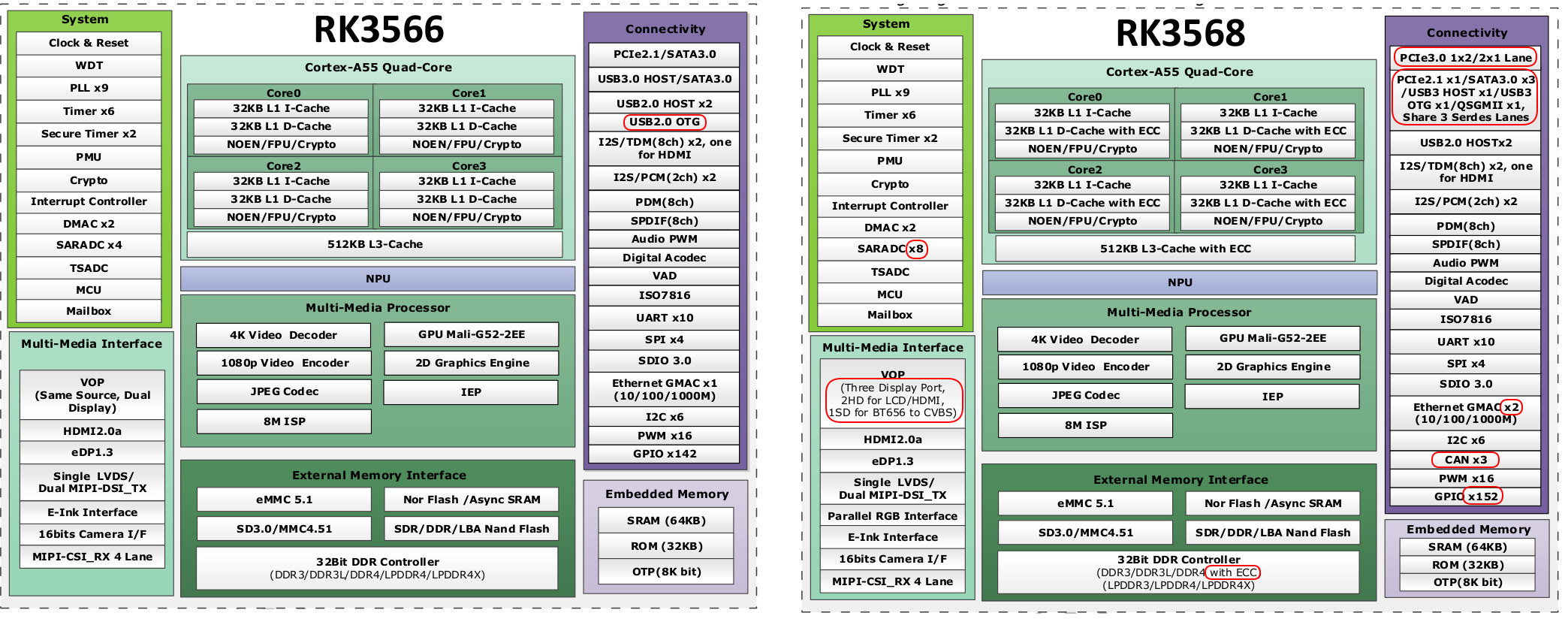
Just look at the source code of the port, all the patches are there in the files directory.
 
the ondisk offset between idbloader.img and u-boot.itb seem to be different (set at compile time) for spi and sd card
the default offset for u-boot.itb for sd cards is 16M which will obviously wont work on a 16M flash (like i have)
This is what I don't understand. You said it before in another thread.

So here is a Rock4 disk:
Code:
@Rock4C:~ # gpart show
=>       40  500118112  nda0  GPT  (238G)
         40      32728        - free -  (16M)
      32768     102400     1  efi  (50M)
     135168  499982984     2  freebsd-ufs  (238G)

So Beginning sector seems to float depending on drive type. 40 sectors here and 64 on other medium.
So this is for bootsector?
Our idbloader gets flashed at sector 64
Then u-boot itb starts at sector 16384 then ends at 32728

What is being offfset here? This stuff only consumes first 16M or 32768sectorsx512bytes right?
Won't that fit on 128MBit SPI flash module? 128/8=16M
 
a gpt entry is 128 bytes and freebsds gpart will refuse to create a scheme with less than 128 entries (because of the standard)
so mbr protection (lba 0) gpt header (lba 1) + 32 sectors of gpt entries = 34
the rest is probably alignment to some multiple of whatever
u-boot its in the free 16 mb starts at 8mb
For u-boot to work on spi flash, you do not need to create a partition table on spi
The partition table is needed on the device from which the secondary loader loader.efi is loaded for FreeBSD or grab for Linux.
For RK356x you can make a bootable SD card or eMMC flash in two ways. U-boot or UEFI.

This is crochet setup for NanoPi-R5C (RK3568)

Code:
# FriendlyELEC NanoPi-R5C Setup
#
TARGET=arm64
TARGET_ARCH=aarch64

# UEFI
BOOT_DIR="nanopi-r5c"
BOOT_PATH="/usr/local/share/edk2/${BOOT_DIR}"

#
# RK356X uses EFI
#
rk356x_partition_image() {
        echo "Installing Partitions on ${DISK_MD}"
        disk_partition_gpt

        if [ -f ${BOOT_PATH}/idblock.bin ] ; then
                echo "Installing EDK2 UEFI ${BOOT_PATH} on ${DISK_MD}"
                dd if=${BOOT_PATH}/idblock.bin of=/dev/${DISK_MD} conv=notrunc bs=512 seek=64    >/dev/null 2>&1
                dd if=${BOOT_PATH}/u-boot.itb  of=/dev/${DISK_MD} conv=notrunc bs=512 seek=20480 >/dev/null 2>&1
                disk_partition_efi_create 32m
        else
                echo "Installing Mainline U-Boot on ${DISK_MD}"
                dd if=${BOOT_PATH}/idbloader.img of=/dev/${DISK_MD} conv=notrunc,sync bs=512 seek=64    >/dev/null 2>&1
                dd if=${BOOT_PATH}/u-boot.itb    of=/dev/${DISK_MD} conv=notrunc,sync bs=512 seek=16384 >/dev/null 2>&1
                disk_partition_efi_create
        fi

        disk_partition_swap_create 128m
        disk_partition_ufs_create

}
strategy_add $PHASE_PARTITION_LWW rk356x_partition_image

# Build & install loader.efi.
strategy_add $PHASE_BUILD_OTHER  freebsd_loader_efi_build
strategy_add $PHASE_BOOT_INSTALL mkdir -p EFI/BOOT
strategy_add $PHASE_BOOT_INSTALL freebsd_loader_efi_copy EFI/BOOT/bootaa64.efi

# Puts the kernel on the FreeBSD ROOT partition.
strategy_add $PHASE_FREEBSD_BOARD_INSTALL board_default_installkernel .

Code:
disk_partition_efi_create ( ) {
    if [ -n "$1" ]; then
       START_ARG="-b $1"
    else
       START_ARG="-b 16m"
    fi

    NEW_EFI_PARTITION=`gpart add -t efi -l efi -a 512k -s 50m ${START_ARG} ${DISK_MD} | sed -e 's/ .*//'` || exit 1
    NEW_EFI_DEVICE=/dev/${NEW_EFI_PARTITION}

    echo "Create EFI partition to ${NEW_EFI_DEVICE}"
    newfs_msdos -L efi ${NEW_EFI_DEVICE}
    disk_created_new FAT ${NEW_EFI_PARTITION}
}

-b start The logical block address where the partition will begin.
 
you don't need partitions on the spi flash but it does not hurt to have them
its easier to update flash and don't have to keep the offsets written

i have the fspi/sfc driver compiled in the kernel and just dd the new binary after i build it directly from freebsd (with dd)
Code:
[titus@generic ~]$ gpart show flash/spi0
=>   40  32688  flash/spi0  GPT  (16M)
     40     24              - free -  (12K)
     64   6144           1  linux-data  (3.0M)
   6208   8192           2  efi  (4.0M)
  14400   4096           3  linux-data  (2.0M)
  18496  14232              - free -  (6.9M)
i dd-ed the efiloader to the second linux-data partition
the efi-part is not used/usefull
there is a patch for u-boot which allows fat file systems on mtd but i can't be arsed to use it
 
Phishfry
For the speeds, PCIe 1.1 is max 250MB/s, 2.0 is 500MB/s for x1. Rock 3C have 2.1 with 1-lane, so it's max at 500MB/s :)
Looking at my speeds, I think they are fine and running at 2.0, I don't have the lane/pcie info on boot as you, but looking here:
Code:
root@rock:~ # pciconf -lcv nvme0
nvme0@pci0:1:0:0:       class=0x010802 rev=0x01 hdr=0x00 vendor=0x1217 device=0x8760 subvendor=0x1217 subdevice=0x0002
    vendor     = 'O2 Micro, Inc.'
    device     = 'FORESEE E2M2 NVMe SSD'
    class      = mass storage
    subclass   = NVM
    cap 01[40] = powerspec 3  supports D0 D3  current D0
    cap 05[50] = MSI supports 16 messages, 64 bit, vector masks
    cap 10[70] = PCI-Express 2 endpoint max data 128(256) RO
                 max read 512
                 link x1(x1) speed 5.0(5.0) ASPM disabled(L0s/L1) ClockPM disabled
    cap 11[b0] = MSI-X supports 16 messages, enabled
                 Table in map 0x10[0x2000], PBA in map 0x10[0x3000]
    ecap 0001[100] = AER 2 0 fatal 0 non-fatal 0 corrected
    ecap 0018[148] = LTR 1
    ecap 001e[150] = L1 PM Substates 1

I think it's running at 2.0 x1, which is max supported by this hardware, so it's just my NVMe disk is allowing

SleepWalker
For the u-boot, you can change default boot_targets and have nvme first (as it default, at least on rock3c to mmc1 mmc0 nvme scsi usb pxe dhcp spi) - there should be define somewhere for that).

I wasn't been able to successfully boot Tianocore EDK2 UEFI on my Rock 3C last time I've checked (I think I've tried quartz images). I saw that Orange 3B board was added in there, maybe I will try and boot that with dtb replaced.
 
On NanoPC-T6

Code:
root@NanoPC-T6:~ # uname -aUK
FreeBSD NanoPC-T6 14.0-RC3 FreeBSD 14.0-RC3 #0 releng/14.0-n265368-c6cfdc130554-dirty: 
root@NanoPC-T6:~ #

Code:
root@NanoPC-T6:~ # pciconf -lv
re0@pci2:1:0:0:    class=0x020000 rev=0x05 hdr=0x00 vendor=0x10ec device=0x8125 subvendor=0x10ec subdevice=0x8125
    vendor     = 'Realtek Semiconductor Co., Ltd.'
    device     = 'RTL8125 2.5GbE Controller'
    class      = network
    subclass   = ethernet
ath0@pci3:1:0:0:    class=0x028000 rev=0x01 hdr=0x00 vendor=0x168c device=0x0034 subvendor=0x1a3b subdevice=0x2234
    vendor     = 'Qualcomm Atheros'
    device     = 'AR9462 Wireless Network Adapter'
    class      = network
re1@pci4:1:0:0:    class=0x020000 rev=0x05 hdr=0x00 vendor=0x10ec device=0x8125 subvendor=0x10ec subdevice=0x8125
    vendor     = 'Realtek Semiconductor Co., Ltd.'
    device     = 'RTL8125 2.5GbE Controller'
    class      = network
    subclass   = ethernet
nvme0@pci0:1:0:0:    class=0x010802 rev=0x01 hdr=0x00 vendor=0x15b7 device=0x5017 subvendor=0x15b7 subdevice=0x5017
    vendor     = 'Sandisk Corp'
    device     = 'WD Black SN770 / PC SN740 256GB / PC SN560 (DRAM-less) NVMe SSD'
    class      = mass storage
    subclass   = NVM
root@NanoPC-T6:~ #

Code:
root@NanoPC-T6:~ # diskinfo -t nda0
nda0
    512             # sectorsize
    500107862016    # mediasize in bytes (466G)
    976773168       # mediasize in sectors
    0               # stripesize
    0               # stripeoffset
    WD_BLACK SN770 500GB    # Disk descr.
    23171H803998    # Disk ident.
    nvme0           # Attachment
    Yes             # TRIM/UNMAP support
    0               # Rotation rate in RPM

Seek times:
    Full stroke:      250 iter in   0.007268 sec =    0.029 msec
    Half stroke:      250 iter in   0.014055 sec =    0.056 msec
    Quarter stroke:      500 iter in   0.022039 sec =    0.044 msec
    Short forward:      400 iter in   0.013948 sec =    0.035 msec
    Short backward:      400 iter in   0.015962 sec =    0.040 msec
    Seq outer:     2048 iter in   0.102081 sec =    0.050 msec
    Seq inner:     2048 iter in   0.072413 sec =    0.035 msec

Transfer rates:
    outside:       102400 kbytes in   0.064429 sec =  1589346 kbytes/sec
    middle:        102400 kbytes in   0.062814 sec =  1630210 kbytes/sec
    inside:        102400 kbytes in   0.062992 sec =  1625603 kbytes/sec

root@NanoPC-T6:~ #

AR9462 Wireless Network Adapter - The only thing I could get to work ;-)
 
Tried Tianocore EDK2 UEFI image for Orange 3B with DTB replaced for rock-3c, it start to boot, but hangs and does not boot from nvme/usb
Code:
DDR Version V1.11 20211103
ln
ddrconfig:0
LP4 MR14:0x4d
LPDDR4, 324MHz
BW=32 Col=10 Bk=8 CS0 Row=15 CS=1 Die BW=16 Size=1024MB

change to: 324MHz
PHY drv:clk:38,ca:38,DQ:30,odt:0
vrefinner:41%, vrefout:41%
dram drv:40,odt:0
clk skew:0x58

change to: 528MHz
PHY drv:clk:38,ca:38,DQ:30,odt:0
vrefinner:41%, vrefout:41%
dram drv:40,odt:0
clk skew:0x60

change to: 780MHz
PHY drv:clk:38,ca:38,DQ:30,odt:0
vrefinner:41%, vrefout:41%
dram drv:40,odt:0
clk skew:0x58

change to: 1560MHz(final freq)
PHY drv:clk:38,ca:38,DQ:30,odt:60
vrefinner:16%, vrefout:29%
dram drv:40,odt:80
clk skew:0x7
out
U-Boot SPL board init
U-Boot SPL 2017.09-gaaca6ffec1-211203 #zzz (Dec 03 2021 - 18:42:16)
unknown raw ID phN
unrecognized JEDEC id bytes: 00, 00, 00
Trying to boot from MMC2
No misc partition
Trying fit image at 0x4000 sector
Not fit magic
Trying fit image at 0x5000 sector
## Verified-boot: 0
## Checking atf-1 0x00040000 ... sha256(fe4f274c06...) + OK
## Checking uboot 0x00a00000 ... OK
## Checking fdt 0x00b00000 ... sha256(704f39da0a...) + OK
## Checking atf-2 0x00068000 ... sha256(8d44036095...) + OK
## Checking atf-3 0xfdcd0000 ... sha256(e410275b51...) + OK
## Checking atf-4 0xfdcc9000 ... sha256(990c53fc01...) + OK
## Checking atf-5 0x00066000 ... sha256(315a4195a9...) + OK
## Checking optee 0x08400000 ... sha256(08e1fd41e1...) + OK
Jumping to U-Boot(0x00a00000) via ARM Trusted Firmware(0x00040000)
Total: 325.560 ms

INFO:    Preloader serial: 2
NOTICE:  BL31: v2.3():v2.3-181-gc9a647cae:cl
NOTICE:  BL31: Built : 10:55:41, Oct 18 2021
INFO:    GICv3 without legacy support detected.
INFO:    ARM GICv3 driver initialized in EL3
INFO:    pmu v1 is valid
INFO:    dfs DDR fsp_param[0].freq_mhz= 1560MHz
INFO:    dfs DDR fsp_param[1].freq_mhz= 324MHz
INFO:    dfs DDR fsp_param[2].freq_mhz= 528MHz
INFO:    dfs DDR fsp_param[3].freq_mhz= 780MHz
INFO:    Using opteed sec cpu_context!
INFO:    boot cpu mask: 0
INFO:    BL31: Initializing runtime services
INFO:    BL31: Initializing BL32
I/TC:
I/TC: OP-TEE version: 3.13.0-595-gf5add58be #hisping.lin (gcc version 10.2.1 202                                                                         01103 (GNU Toolchain for the A-profile Architecture 10.2-2020.11 (arm-10.16))) #                                                                         26 Tue Dec 21 15:50:44 CST 2021 aarch64
I/TC: Primary CPU initializing
I/TC: Primary CPU switching to normal world boot
INFO:    BL31: Preparing for EL3 exit to normal world
INFO:    Entry point address = 0xa00000
INFO:    SPSR = 0x3c9
DDR Version V1.11 20211103
ln
ddrconfig:0
LP4 MR14:0x4d
LPDDR4, 324MHz
BW=32 Col=10 Bk=8 CS0 Row=15 CS=1 Die BW=16 Size=1024MB

change to: 324MHz
PHY drv:clk:38,ca:38,DQ:30,odt:0
vrefinner:41%, vrefout:41%
dram drv:40,odt:0
clk skew:0x58

change to: 528MHz
PHY drv:clk:38,ca:38,DQ:30,odt:0
vrefinner:41%, vrefout:41%
dram drv:40,odt:0
clk skew:0x60

change to: 780MHz
PHY drv:clk:38,ca:38,DQ:30,odt:0
vrefinner:41%, vrefout:41%
dram drv:40,odt:0
clk skew:0x58

change to: 1560MHz(final freq)
PHY drv:clk:38,ca:38,DQ:30,odt:60
vrefinner:16%, vrefout:29%
dram drv:40,odt:80
clk skew:0x6
out
U-Boot SPL board init
U-Boot SPL 2017.09-gaaca6ffec1-211203 #zzz (Dec 03 2021 - 18:42:16)
unknown raw ID phN
unrecognized JEDEC id bytes: 00, 00, 00
Trying to boot from MMC2
No misc partition
Trying fit image at 0x4000 sector
Not fit magic
Trying fit image at 0x5000 sector
## Verified-boot: 0
## Checking atf-1 0x00040000 ... sha256(fe4f274c06...) + OK
## Checking uboot 0x00a00000 ... OK
## Checking fdt 0x00b00000 ... sha256(704f39da0a...) + OK
## Checking atf-2 0x00068000 ... sha256(8d44036095...) + OK
## Checking atf-3 0xfdcd0000 ... sha256(e410275b51...) + OK
## Checking atf-4 0xfdcc9000 ... sha256(990c53fc01...) + OK
## Checking atf-5 0x00066000 ... sha256(315a4195a9...) + OK
## Checking optee 0x08400000 ... sha256(08e1fd41e1...) + OK
Jumping to U-Boot(0x00a00000) via ARM Trusted Firmware(0x00040000)
Total: 325.570 ms

INFO:    Preloader serial: 2
NOTICE:  BL31: v2.3():v2.3-181-gc9a647cae:cl
NOTICE:  BL31: Built : 10:55:41, Oct 18 2021
INFO:    GICv3 without legacy support detected.
INFO:    ARM GICv3 driver initialized in EL3
INFO:    pmu v1 is valid
INFO:    dfs DDR fsp_param[0].freq_mhz= 1560MHz
INFO:    dfs DDR fsp_param[1].freq_mhz= 324MHz
INFO:    dfs DDR fsp_param[2].freq_mhz= 528MHz
INFO:    dfs DDR fsp_param[3].freq_mhz= 780MHz
INFO:    Using opteed sec cpu_context!
INFO:    boot cpu mask: 0
INFO:    BL31: Initializing runtime services
INFO:    BL31: Initializing BL32
I/TC:
I/TC: OP-TEE version: 3.13.0-595-gf5add58be #hisping.lin (gcc version 10.2.1 20201103 (GNU Toolchain for the A-profile Architecture 10.2-2020.11 (arm-10.16))) #26 Tue Dec 21 15:50:44 CST 2021 aarch64
I/TC: Primary CPU initializing
I/TC: Primary CPU switching to normal world boot
INFO:    BL31: Preparing for EL3 exit to normal world
INFO:    Entry point address = 0xa00000
INFO:    SPSR = 0x3c9

any tips how to debug this?
 
Does a logo appear on HDMI?
You need to build UEFI with the debug key enabled

To create UEFI for Rock 3C,
You need to do this using the example of Orange Pi 3B
You need to change the contents of two files.

1. OrangePi3B.dsс

Here 4 lines have meaning, they can be taken from DTS for Orange Pi 3B

2. https://github.com/jaredmcneill/qua...rangePi3B/Drivers/BoardInitDxe/BoardInitDxe.c
 
Nothing on HDMI, tried to build DEBUG target, but it failed "the required fv image size 0xe0498 exceeds the set fv image size 0xe0000"
 
I think it's running at 2.0 x1,
Yes it is running PCIe Gen2.

speed 5.0(5.0)
2.5=Gen1
5.0=Gen2
8.0=Gen3

My pciconf -lvbce
Code:
nvme0@pci0:1:0:0:    class=0x010802 rev=0x01 hdr=0x00 vendor=0x1344 device=0x5410 subvendor=0x1344 subdevice=0x0100
    vendor     = 'Micron Technology Inc'
    device     = '2200S NVMe SSD'
    class      = mass storage
    subclass   = NVM
    bar   [10] = type Memory, range 64, base 0xfa000000, size 16384, enabled
    cap 10[80] = PCI-Express 2 endpoint max data 128(256) FLR RO NS
                 max read 512
                 link x4(x4) speed 5.0(8.0) ASPM disabled(L1)
    cap 11[d0] = MSI-X supports 32 messages, enabled
                 Table in map 0x10[0x3000], PBA in map 0x10[0x3200]
    cap 05[e0] = MSI supports 1 message, 64 bit
    cap 01[f8] = powerspec 3  supports D0 D3  current D0
    ecap 000b[100] = Vendor [1] ID 1556 Rev 1 Length 8
    ecap 0018[108] = LTR 1
    ecap 001e[110] = L1 PM Substates 1
    ecap 0001[200] = AER 1 0 fatal 0 non-fatal 0 corrected
    ecap 0019[300] = PCIe Sec 1 lane errors 0
 
link x1(x1)
This seems lower than specs right? I am showing x4 on my RK3399.
Which don't seem right I thought x2 was max on RK3399.
Code:
nda0: nvme version 1.2 x4 (max x4) lanes PCIe Gen2 (max Gen3) link

Edit; I was wrong x4 PCIe 2.1 on RK3399.

RK3399 features 4-Lanes PCI-E 2.1​

 
Here is another Rock4B I have built. 2TB Intel NVMe 670p.

pciconf -lvbce
Code:
nvme0@pci0:1:0:0:    class=0x010802 rev=0x03 hdr=0x00 vendor=0x8086 device=0xf1aa subvendor=0x8086 subdevice=0x390f
    vendor     = 'Intel Corporation'
    class      = mass storage
    subclass   = NVM
    bar   [10] = type Memory, range 64, base 0xfa000000, size 16384, enabled
    cap 01[40] = powerspec 3  supports D0 D3  current D0
    cap 05[50] = MSI supports 8 messages, 64 bit, vector masks
    cap 10[70] = PCI-Express 2 endpoint max data 128(512) FLR RO
                 max read 512
                 link x4(x4) speed 5.0(8.0) ASPM disabled(L1) ClockPM disabled
    cap 11[b0] = MSI-X supports 16 messages, enabled
                 Table in map 0x10[0x2000], PBA in map 0x10[0x2100]
    ecap 0001[100] = AER 2 0 fatal 0 non-fatal 0 corrected
    ecap 000e[158] = ARI 1
    ecap 0019[168] = PCIe Sec 1 lane errors 0
    ecap 0010[188] = SR-IOV 1 IOV disabled, Memory Space disabled, ARI disabled
                     0 VFs configured out of 6 supported
                     First VF RID Offset 0x0002, VF RID Stride 0x0001
                     VF Device ID 0x2265
                     Page Sizes: 4096 (enabled), 8192, 65536, 262144, 1048576, 4194304
    ecap 0018[1c8] = LTR 1
    ecap 001e[1d0] = L1 PM Substates 1
ro

diskinfo -t
Code:
Transfer rates:
    outside:       102400 kbytes in   0.108553 sec =   943318 kbytes/sec
    middle:        102400 kbytes in   0.107116 sec =   955973 kbytes/sec
    inside:        102400 kbytes in   0.106738 sec =   959358 kbytes/sec

dmesg
Code:
nda0: <INTEL SSDPEKNU020TZ 002C PHKA3xxxxxxxxx>
Trying to mount root from ufs:/dev/nda0p2 [rw]...
nda0: Serial Number PHKA3xxxxx
nda0: nvme version 1.4 x4 (max x4) lanes PCIe Gen2 (max Gen3) link
nda0: 1953514MB (4000797360 512 byte sectors)
 
It sounded to me like there is a software PCIe multiplexer involved on RK356x so maybe provision more lanes to NVMe.
I wonder how that works.
 
Replaced logo with smaller one, got DEBUG build, nothing more on the serial output.

Phishfry Radxa hardware docs say this board have PCIe 2.1 with 1-lane - I have ROCK 3C, not 4B, that's diffrent board. What wonder me, is why I don't have that extra info about lane/pcie gen in dmesg on boot, but anyway it won't get faster that it already is :)
I remember that many Radxa boards have the feature of working with a connected UART TTL.
In order to avoid errors, you must follow the switching sequence.
It looks like this...
If, with UART TTL connected to your host computer, you pull out the power plug and plug it in again,
the board will not start and you will not see anything on the console.
This is due to the stray voltage entering the board via the UART TTL.
To restart the board you need.
1. Pull out the power cable.
2. Pull out USB UARL TTL serial from host PC
3. Insert USB UARL TTL to host PC
4. Turn on the power.
I was so tired of this that I threw my Radxa Rock-3A into the far corner.
Maybe this will help you for Rock-3C too.
 
have you tried the sdhci and eqos patches ?
I'm trying to understand why recording on eMMC doesn't work for me.
I apply patches, fix DTS, assemble a new kernel and DTB, run the test.
I see an increase in eMMC read speed to 150Mbps, but the read-only mode is active.
I can't understand what my mistake is. I'm testing on Radxa-E25,
I don't have Rock-3C or Orange-3B yet.

By the way, almost all DTS files for RK356x boards have errors that lead to kernel panic.
This applies to NanoPC-R5S/R5C, Radxa E25, Radxa 23, Rock 3A

Code:
--- a/sys/contrib/device-tree/src/arm64/rockchip/rk3568-radxa-cm3i.dtsi
+++ b/sys/contrib/device-tree/src/arm64/rockchip/rk3568-radxa-cm3i.dtsi
@@ -94,20 +94,25 @@
 
 &cpu0 {
        cpu-supply = <&vdd_cpu>;
+       clocks = <&cru ARMCLK>;
 };
 
 &cpu1 {
        cpu-supply = <&vdd_cpu>;
+       clocks = <&cru ARMCLK>;
 };
 
 &cpu2 {
        cpu-supply = <&vdd_cpu>;
+       clocks = <&cru ARMCLK>;
 };
 
 &cpu3 {
        cpu-supply = <&vdd_cpu>;
+       clocks = <&cru ARMCLK>;
 };
 
+#if 0
 &display_subsystem {
        status = "disabled";
 };
@@ -116,6 +121,7 @@
        mali-supply = <&vdd_gpu>;
        status = "okay";
 };
+#endif
 
 &i2c0 {
        status = "okay";
@@ -142,9 +148,18 @@
                reg = <0x20>;
                interrupt-parent = <&gpio0>;
                interrupts = <RK_PA3 IRQ_TYPE_LEVEL_LOW>;
+
                #clock-cells = <1>;
+               clock-output-names = "rk808-clkout1", "rk808-clkout2";
+               // fb-inner-reg-idxs = <2>;
+               /* 1: rst regs (default in codes), 0: rst the pmic */
+               pmic-reset-func = <0>;
+               /* not save the PMIC_POWER_EN register in uboot */
+               not-save-power-en = <1>;
+
                pinctrl-names = "default";
                pinctrl-0 = <&pmic_int>;
+
                rockchip,system-power-controller;
                wakeup-source;
 
@@ -381,7 +396,14 @@
        status = "okay";
 };

+clocks = <&cru ARMCLK>; - enables cpu freq control Without patch for scmi-smc

I will test eqos when I calm down a little, I have to find a lot of errors in our DTS without fixing which the kernel simply does not start.

Here is my DTS files, and patches:
 

Attachments

  • patch-rk3568-radxa-cm3i.dtsi.txt
    1.8 KB · Views: 54
  • patch-rk3568-radxa-e25.dts.txt
    631 bytes · Views: 53
  • rk3568-radxa-cm3i.dtsi.txt
    8.8 KB · Views: 50
  • rk3568-radxa-e25.dts.txt
    4.6 KB · Views: 51
Last edited:
What about disable-wp (write protect) node. I don't see one in your output.
C:
root@NanoPC-T6:/usr/src/sys/contrib/device-tree/src/arm64/rockchip # tail +180 rk3568-radxa-e25.dts | head -15

&sdmmc0 {
    bus-width = <4>;
    cap-sd-highspeed;
    cd-gpios = <&gpio0 RK_PA4 GPIO_ACTIVE_LOW>;
    /* Also used in pcie30x1_clkreqnm0 */
    disable-wp;
    pinctrl-names = "default";
    pinctrl-0 = <&sdmmc0_bus4 &sdmmc0_clk &sdmmc0_cmd>;
    sd-uhs-sdr104;
    vmmc-supply = <&vcc3v3_sd>;
    vqmmc-supply = <&vccio_sd>;
    status = "okay";
};

done
 
bug in rk_tsadc.c causes reboot
/sys/arm64/rockchip/rk_tsadc.c#L486
in the first line should be tsadc_temp_to_raw instead of tsadc_raw_to_temp
the way its set for the alarm value

writing a bogus value causes a reboot when shutdown_mode is 0 (cru)
on rk3566. could cause the same effect on other boards too


val = tsadc_raw_to_temp(sc, sc->shutdown_temp);
WR4(sc, TSADC_COMP_SHUT(sensor->channel), val);
val = RD4(sc, TSADC_AUTO_CON);
val |= TSADC_AUTO_SRC_EN(sensor->channel);
WR4(sc, TSADC_AUTO_CON, val);

/* Alarm temperature */
val = tsadc_temp_to_raw(sc, sc->alarm_temp);
WR4(sc, TSADC_COMP_INT(sensor->channel), val);
val = RD4(sc, TSADC_INT_EN);
val |= TSADC_COMP_INT_SRC_EN(sensor->channel);
WR4(sc, TSADC_INT_EN, val);

or set
rockchip,hw-tshut-mode = <0x1>;
in the dtb because the gpio probably won't work
0 means cru reset and will reboot the system just after tsadc is probed
 
Back
Top