Crochet is the best. Edit your source files and run crochet script and write image and test.How do I best build the kernel, on my other FreeBSD machine
The RPi3 uses a newer method for adding devices. Instead of dts you add devices to dto(device tree overlay) in root directory.Is there an easier way to configure the three ow... modules without a rebuild?
Yes this is all you need. Edit the dts (or use the dto method for Pi3) and add your "ow" modules to RPi's kernconf.says I have to now go into the kernel source, edit the pin assignment into my DTS file, add those four modules to the device list in another file, and rebuild everything.
Any accessory you want to work you need to compile in support. Even a Real Time Clock module.Are there good general reasons to compile your own kernels
pkg install git u-boot-rpi2
git clone https://www.github.com/freebsd/crochet /crochet
cd /crochet
./crochet.sh -b RaspberryPi2  /*The first time run takes many hours */
cd /crochet/work
dd if=<your image name> of=/dev/<your device>Yes this is all you need. Edit the dts (or use the dto method for Pi3) and add your "ow" modules to RPi's kernconf.
The FreeBSD source is the same for all versions(amd64/i386/arm).
Don't let the lack of a FreeBSD12-ARM package repository distract you. Not so long ago there was no official ARM repository.
All versions pull from the same ports tree anyway.
Any accessory you want to work you need to compile in support. Even a Real Time Clock module.
There is no Plug and Play. It's all static with FDT..
https://wiki.freebsd.org/FlattenedDeviceTree
My method is do the dts edits and add modules to kernconf and use crochet to crosscompile.
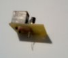
kldloadOK, Thank youI could not get OneWire working with RPi3 or on either GPIO supported x86 platform, MBM or APU.
bytgpio_load="YES"
hint.owc.0.at=gpiobus0
#hint.owc.0.pin_list="0x003E ; 0x003F"
hint.owc.0.pin_list="62"
ow_load="YES"
owc_load="YES"
ow_temp_load="YES" dmesgowc0: <GPIO one-wire bus> at pin 62 on gpiobus0
ow0: <1 Wire Bus> on owc0
ow_temp0: <Advanced One Wire Temperature> romid 28:ff:4d:83:70:16:05:8a on ow0
ow_temp1: <Advanced One Wire Temperature> romid 28:ff:2d:04:71:16:04:31 on ow0
ow_temp0: Running in parasitic mode unsupported
ow_temp2: <Advanced One Wire Temperature> romid 28:ff:47:56:70:16:05:b7 on ow0
ow_temp1: Running in parasitic mode unsupported grep ow_temp | grep temperaturedev.ow_temp.2.temperature: 24.125C
dev.ow_temp.1.temperature: 24.125C
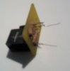
dev.ow_temp.0.temperature: 23.250COne-wire works over, well, one wire, so it uses a single pin. Why did you want to give it another pin?I was trying in vain to add a second pin for OneWire support but couldn't get it working. Neither decimal or hex.
When a circuit has both analog and data, it's sometimes a good idea to keep data ground separate to keep any possible noise out of the other.Why do some designs have an 'data ground'?
I have a project of twelve DS1820 sensors I want to monitor. Any more than 10 devices per pin gives me trouble..Why did you want to give it another pin?
The numbers can be decimal or hexa-decimal with 0x prefix.
Any non-digit character can be used as a separator.
For example,
it can be a comma, a slash or a space. The
separator can be followed by any number of
space characters.
Multiple pins are supported in general, e.g. I2C bit banging requires two pins.The manual for gpio(4) seems to indicate that multiple pins are OK
hint.driver.unit.pin_list
I was hoping the same for this setting:
"hint.owc.0.pin_list="
I am using ow_temp with one group of sensors inside with another group of ds1820 sensors outdoors.But what do you want to achieve with multiple pins for one-wire protocol? That was my question.