Looking for proper cable for Graceful / Safe Shutdown of server

Hi, FreeBSD Gurus!

Looking for proper cable for Graceful / Safe Shutdown of server:

on a SDU/PDU there are several RJ11 ports and manual says tat device able to sending “Safe Shutdown” signal to any PC/server that have an a COM-port and able to make “Graceful Shutdown”.
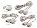
So from one side of cable there must be are RJ11, and the DB9 on opposite end. But I do not know the pinout.

2.
Which daemon / port / package best to solving my problem ?
And sub-question: is NUT better than apccups in my case with cable connection?

So, the question is what is proper pinout cable and software for Graceful / Safe Shutdown of FreeBSD server?
(is it null-modem with full handshaking or with half-handshaking?...)

UPDATE
Unfortunately, I cannot able to find ANY information regarding that RJ11 connector in ANY user manuals/tech docs on that particular PDU, legacy and newest PDUs from that company.... Spending around 4h of total screen time :)

But I asking here because have a tough that in nowadays that may be something standardized, like this, because most of hardware solutions made from “other OEM blocks”.

P.S.
I have a little bit equipment in a lab, two hands and not stupid (I hope) head, so I able to doing cable myself. ;)
 
UPDATE
As I able to know from

UPS Signalling Bundle for IBM AS/400 & IBMi (IBM Power Systems)

document, there are some standard in UPS signaling, like

  • If the value is 0 - no UPS is detected.
  • If the value is 8 - UPS detected and everything is normal.
  • If the value is 9 - UPS detected and battery is low.
  • If the value is A - UPS detected and in bypass mode.
  • If the value is B - UPS detected, in bypass mode, and battery is low.
  • If the value is C - UPS detected and power has failed.
  • If the value is D - UPS detected, power has failed, and battery is low.

If this real, may be not ordinary 3-wire used, but all 9 pins?
 

Attachments

  • 276AE7CE-1E56-443D-BB5B-34754E2ACC77.jpeg
    276AE7CE-1E56-443D-BB5B-34754E2ACC77.jpeg
    35.7 KB · Views: 59
i sometimes wrote an UPS monitoring program for a local manufacturer
it used DCD and CTS for signaling
Code:
#define UPS_NORMALOP   (TIOCM_CAR | TIOCM_CTS)
#define UPS_BATTERYOP  (TIOCM_CAR)
#define UPS_BATTERYLOW 0

#define UPS_MASK (TIOCM_CAR | TIOCM_CTS)
 
Depends heavily on which UPS you are using. Some use the serial TX/RX lines and have a real protocol (with messages sent back and forth). I used to the have a "Best" FerrUps (those use giant ferroresonant transformers), and it had a real serial port with a DB9 or DB25 connector. Others use just a few modem control pins, as covecat said. Modern ones are typically USB, not serial. For example, the cheap APC USB (model ES550) I have at home has a USB port, but uses an 8-pin RJ45 connector for USB (!), requiring a specialized cable.

You'll have to find documentation; I know of no standardization here.
 
Thank You for answering!
Depends heavily on which UPS you are using. Some use the serial TX/RX lines and have a real protocol (with messages sent back and forth).
Primary the GE, Liebert, Emerson (Schneider nowadays), Eaton.

I used to the have a "Best" FerrUps (those use giant ferroresonant transformers), and it had a real serial port with a DB9 or DB25 connector. Others use just a few modem control pins, as covecat said. Modern ones are typically USB, not serial. For example, the cheap APC USB (model ES550) I have at home has a USB port, but uses an 8-pin RJ45 connector for USB (!), requiring a specialized cable.
I have opinion on this: due economical reasons (to minimize labor & production & R&D costs), most manufacturers nowadays using the OLD SCHEMATIC (but new elements), but cut off all rarely used functions even in Enterprise segment.

Anyway, because the numbers of manufacturers for Enterprise are a little few, some low-level standardization MUST exist.
Because for example Liebert/Schneider NEED to be able used with Eaton, Schneider or ServerTech...

You'll have to find documentation; I know of no standardization here.
I try several times. Only after no success - wrote here on forum.
UPDATE
Wiring Specifications Connection
Supported Wire Type
Max. Lenght
1.
RS-232
Null Modem Cable
50 ft. (15.3m)
2.
DB9F Connector
DTE Null Modem Cable
50 ft. (15m)
 
The "Best" UPS I had is today an Eaton, but it is completely obsolete. It was a genius design: Take a ferro-resonant transformer and a really big capacitor, and build a tank circuit (an LC resonator), which stores lots of energy at exactly the line frequency (60 Hz here). When the system is running on utility power, the LC resonator is a fabulously good band pass filter, which makes the power going to the computer be very clean. When power fails, the tank has enough energy to get through a small number of cycles. In the meantime, the battery-powered circuit starts up, and it sends a synchronized 60Hz signal to the transformer in the LC circuit, which now feeds the output. The beauty is that the transformer takes care of going from 12V or 48V to 120 or 240 V, without needing any high-frequency DC/DC converter. And the battery-powered power can be a square wave (bang-bang), because the LC resonator will low-pass filter it into a sine wave. The drawback of this system are sadly also obvious: The L is a really big and heavy transformer (my 1.5 kVA UPS weighed about 200 lbs), the capacitors are huge expensive and short-lived, and having the LC resonator in the circuit all the time eats significant power (a few percent of rated load at all time).

Anyway, you said "some low-level standardization must exist". I love your optimism! I think it's more likely that there is only a handful of UPS interface (controller) manufacturers, and those entities that connect to those UPSes simply have learned to deal with the handful of interfaces.

To get further: Can you tell us exactly what model the UPS is? From the document you linked, it seems that it is an APC, but that doesn't tell us very much; APC uses a mix of USB and serial ports, and the big UPSes have little slide-in boards that can go directly to Ethernet and SNMP. And: On the "RJ11" port, are you sure it is RJ11? Or might it be RJ45? Does it have 4, 6 or 8 pins? How wide is it? I actually suspect that what you have is an 8-pin connector on your UPS, which makes it likely that the connection is not actually serial, but either Ethernet or USB.
 
The "Best" UPS I had is today an Eaton, but it is completely obsolete. It was a genius design: Take a ferro-resonant transformer and a really big capacitor, and build a tank circuit (an LC resonator), which stores lots of energy at exactly the line frequency (60 Hz here). When the system is running on utility power, the LC resonator is a fabulously good band pass filter, which makes the power going to the computer be very clean. When power fails, the tank has enough energy to get through a small number of cycles. In the meantime, the battery-powered circuit starts up, and it sends a synchronized 60Hz signal to the transformer in the LC circuit, which now feeds the output. The beauty is that the transformer takes care of going from 12V or 48V to 120 or 240 V, without needing any high-frequency DC/DC converter. And the battery-powered power can be a square wave (bang-bang), because the LC resonator will low-pass filter it into a sine wave. The drawback of this system are sadly also obvious: The L is a really big and heavy transformer (my 1.5 kVA UPS weighed about 200 lbs), the capacitors are huge expensive and short-lived, and having the LC resonator in the circuit all the time eats significant power (a few percent of rated load at all time).
Wow!
Thank You so much about so detailed explanation!

Did You know that small (7-18kVa) or a little big (20-40kVa) models of FerrUPS exist now?

Anyway, you said "some low-level standardization must exist". I love your optimism!
Thank You, I love it so! :) This help me not going crazy in IT last 40+ years ;)

I think it's more likely that there is only a handful of UPS interface (controller) manufacturers, and those entities that connect to those UPSes simply have learned to deal with the handful of interfaces.
Right. Because of this logic I thinking that for example data cable from Eaton = data cable from Schneider = data cable from Liebert...
Like “non-formal standard”.

To get further: Can you tell us exactly what model the UPS is? From the document you linked, it seems that it is an APC, but that doesn't tell us very much; APC uses a mix of USB and serial ports, and the big UPSes have little slide-in boards that can go directly to Ethernet and SNMP.
You are absolutely right.

I tell You more: in Enterprise connectivity/management/monitoring cards USB Type-C nowadays also used in mix with RJ45, RJ11 (mostly for leak/humidity sensors) and USB-A male, USB-B female.

A little bit of madness...
And: On the "RJ11" port, are you sure it is RJ11? Or tit be RJ45? Does it have 4, 6 or 8 pins? How wide is it?
RJ11
6 pin (43-carats gold plated in Taiwan ;)
I actually suspect that what you have is an 8-pin connector on your UPS, which makes it likely that the connection is not actually serial, but either Ethernet or USB.
Back to the first message on this tread, the CDU/PDU have this RJ11 and server must be connected to this Altuseen CDU/PDU by DB9/COM.

Initially CDU/PDU receive signal on RS232/DB9 to shutdown from Liebert UPC trought DB9-DB9 cable.

So one of “shutdown” chain are UPS -> CDU/PDU -> server COM port.
On Altusen CDU/PDU there are RJ11 really, trust me! ;)
 
No idea how to debug this without having a model number and documentation.

Suggestion: The RJ11 is probably serial, as you said, since it can be connected to RJ11. So start by figuring out what the 6 pins are. One of them must be ground, and you can find out which with an ohmmeter against the frame ground. Now use a voltmeter to look at the pins: Some of them will have -12V or +12V (roughly, might be 9 or 10V instead). Those must be outputs. The others will have near zero volts, and must be inputs. Since there are at most 5 pins left, this won't be very hard. You might even find a pin or two that are completely disconnected. If you get lucky, there are two input pins, two output pins, one ground, one disconnected. Now look at the pinout of a DB9 connector, for example by searching the web for "RJ11 to DB9 UPS cable pinout". There are only a few places each of the input and output pins can go. If there are two inputs or outputs, you probably only have to try two options (AB or BA); if there are three pins, there are only 6 possibilities (ABC, ACB, BAC, BCA, CAB, CBA). So in total there are probably a dozen or less combinations to explore. Solder them up one at a time, and see whether you get any communication with standard UPS software going. This will take half a day.

To make it a little faster: You can find little boxes that have two DB9 connectors (one male one female), and lots of little LEDs, one for each line. Get one of those, and use it to debug whether the connections you made make any sense. For example, when you connect to the serial line, RTS and CTS should toggle once. On the other hand, Tx and Rx should blink really fast when there is traffic. If you see RTS or DCD or one of those blink really fast, you soldered it wrong.

For this way of debugging, you'll need lots and lots of patience.
 
I think that without documentation, you are going to struggle.

20 years ago I modified FreeBSD getty(8) to alert when a mis-behaving UPS in a data centre switched into "bypass" mode (feeding raw, unconditioned power into the racks). But I had the UPS manual, knew what pin went high when that happened, and knew it was TTL voltage levels (good enough for RS232 signaling) so wired it to pin 8 (Carrier Detect) on a DB25 tty port. Getty wakes up when it sees CD...

These days I just connect a USB port on the UPS to a USB port on a FreeBSD server and configure sysutils/nut.
 
At the first: THANK YOU SO MUCH!!!! for this very detailed step-by-step guide :) And for Your patience!
No idea how to debug this without having a model number and documentation.
Altusen PN9108

Suggestion: The RJ11 is probably serial, as you said, since it can be connected to RJ11. So start by figuring out what the 6 pins are. One of them must be ground, and you can find out which with an ohmmeter against the frame ground. Now use a voltmeter to look at the pins: Some of them will have -12V or +12V (roughly, might be 9 or 10V instead). Those must be outputs. The others will have near zero volts, and must be inputs. Since there are at most 5 pins left, this won't be very hard. You might even find a pin or two that are completely disconnected. If you get lucky, there are two input pins, two output pins, one ground, one disconnected. Now look at the pinout of a DB9 connector, for example by searching the web for "RJ11 to DB9 UPS cable pinout". There are only a few places each of the input and output pins can go. If there are two inputs or outputs, you probably only have to try two options (AB or BA); if there are three pins, there are only 6 possibilities (ABC, ACB, BAC, BCA, CAB, CBA). So in total there are probably a dozen or less combinations to explore. Solder them up one at a time, and see whether you get any communication with standard UPS software going. This will take half a day.
I have a little bit knowledge on this :) May be 3h or less

To make it a little faster: You can find little boxes that have two DB9 connectors (one male one female), and lots of little LEDs, one for each line. Get one of those, and use it to debug whether the connections you made make any sense. For example, when you connect to the serial line, RTS and CTS should toggle once. On the other hand, Tx and Rx should blink really fast when there is traffic. If you see RTS or DCD or one of those blink really fast, you soldered it wrong.
Perfect idea with LEDs. I’ll go to my boxes with electronics parts in warehouse:)

For this way of debugging, you'll need lots and lots of patience.
I’m ok with this:
a) no much longer that our life :)
b) weekend are coming, and no BBQ on backyard, so I have a time ;)

Thank You again one time!
 
I think that without documentation, you are going to struggle.
Because of age,- only User Manual, no any Schematic...
20 years ago I modified FreeBSD getty(8) to alert when a mis-behaving UPS in a data centre switched into "bypass" mode (feeding raw, unconditioned power into the racks). But I had the UPS manual, knew what pin went high when that happened, and knew it was TTL voltage levels (good enough for RS232 signaling) so wired it to pin 8 (Carrier Detect) on a DB25 tty port. Getty wakes up when it sees CD...
Let’s note, YOU HAVE AN AMAZING MEMORY ;) Are You have Your brain upgraded by extra memstick ? :)

These days I just connect a USB port on the UPS to a USB port on a FreeBSD server and configure sysutils/nut.
BTW, on Your opinion, are monitoring by NUT faster/stable on USB rather COM ?
 
The documentation for that is online: https://assets.aten.com/product/manual/pn9108-s_2014-05-30.pdf
And it shows a DB9 connection, not RJ11. So what piece of equipment has the RJ11?
Better to see “Diagram” section on this white paper http://static.mercateo.com/b3/dcicontent/pdf/P211800.PDF?v=2

8 x 6-pin RJ11 for attaching Safe / Graceful Shutdown cable.

Or does that documentation not match your hardware?
Exactly. And this white paper also http://static.mercateo.com/b3/dcicontent/pdf/P211800.PDF?v=2
 
I have no experience of using anything but USB on modern UPSs, so don't have an opinion.
I still thinking that COM connection would be a little bit faster because no need to waisting time on USB<~>COM converting in passive type adapter.
But this is not true in case additional monitoring/management card using: the conversion from COM or USB signal to internal always happens.

Have you checked the NUT Hardware compatibility list for your UPS models?
Not find exactly Altusen, but EATON exist.

The NUT development community is generally very supportive.
Thank You for advice!
 
Back
Top