ITE IT8772E GPIO

Hello everyone!
I got an Acer XC-704 computer that uses an N3150 CPU. Motherboard made by Acer.
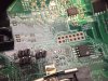
It has a ITE IT8772E I/O chip. This has a breakout for two GPIO pins on the motherboard. I'd very very much want to use them to control some relays.
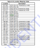
I traced them to pin 63/64 of the IT8772E chip.
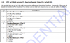
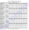
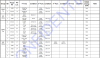
I found the datasheet:
There's some info from the datasheet I attached.
I am using pfSense 2.4.4 which is based on FreeBSD 11.2-RELEASE-p3. I have freeBSD 11.2 in a virtual machine if I need to compile something etc.
Any idea how I could control the pins? I need on/off, and be able to control them from a script.
Any idea is welcomed.
Thank you!

*edit: would have used any LED control line but don't have any, only pci-e network card status LEDs.
superiotool detects the chip and its address:
Bash:
Found ITE IT8772F (id=0x8772, rev=0x1) at 0x2e
 

Attachments

  • Capture7.PNG
    Capture7.PNG
    46.6 KB · Views: 456
  • Capture6.PNG
    Capture6.PNG
    39.6 KB · Views: 236
  • Capture5.PNG
    Capture5.PNG
    137.3 KB · Views: 201
  • Capture4.PNG
    Capture4.PNG
    79.5 KB · Views: 175
  • Capture3.PNG
    Capture3.PNG
    11.1 KB · Views: 193
A quick look at those pin descriptions (CTS, RI) suggest that they are used by serial port 1 ... the alternative GP function depends on the chip's software configuration registers which I suspect are set by something (BIOS?) after power on/a reset. The effect of that is troubling if you plan connecting them in some way to a relay of any sort.
 
I can see UART1 on the board, and its header is not populated. It goes to the bios eeprom.
I was thinking that if they mounted those headers, they maybe planned to use the pins for leds or something like that.
I am playing with acpi_ibm but even loading the module to kernel I still get nothing extra. Maybe I should replace the pci address value before compiling it?
I will maybe try to update the bios while sniffing those pins to see if there is any activity while UART1 is in use.
 

Attachments

  • capture.jpg
    capture.jpg
    1.7 MB · Views: 566
I could also edit the asl file after I dump it, but that's way over my head.
I've tried compiling mbmon but doesn't find anything. Maybe I need to modify the sens_it87.c file from /usr/ports/sysutils/xmbmon/work/xmbmon205 ?
First I want to at least "see" the chip.
How would I go? where should I add 0x2E address that the chip is found under?
 
I find it curious that GPIO1 and GPIO2 appear with two double pin headers which implies jumpers. Does the motherboard manual shed any light on them? If not, I would contact Acer support.
 
You would need a GPIO driver for the ITE8772 for anything to work.
We only have userland support for GPIO on i386/amd64 for MinnowboardMax/Turbot and APU1/2/3

Also be advised that motherboard resources like HDD LED and Power LED are considered "system GPIO" and not user GPIO.
That is probably what the two jumpers that are pictured do. Front Panel LED.
I would hook up a LED to those and see what it does. Keep in mind HDD LED and Power LED's activity.
 
You would need a GPIO driver for the ITE8772 for anything to work.
some variants of acpi_xxxx drivers have for example the logo light on/off, that's useful, could copy the settings for the second channel etc.
sorry for late answering but I am new here and apparently a mod needs to ok my messages atm.
 
Yes exactly ACPI controls the system GPIO.
For userland gpio use we have gpioctl(8)
To use this you need to have a driver.
FreeBSD is very versatile so I am sure you could hack something together if you know programming.
The Minnowboard is ACPI driven GPIO so look at usr/src/sys/dev/gpio/bytgpio.c source for hints.
 
Thank you for the info!
I will have a look. Not much into programming but I've done some simple stuff, arduino/shell scripts etc.
Maybe with help from you guys I'll manage to get it working. It's bugging me because it's right there, I only need two gpio pins for relays and I'd feel bad getting another gpio board in there.
 
You would need a GPIO driver for the ITE8772 for anything to work.
We only have userland support for GPIO on i386/amd64 for MinnowboardMax/Turbot and APU1/2/3

Also be advised that motherboard resources like HDD LED and Power LED are considered "system GPIO" and not user GPIO.
That is probably what the two jumpers that are pictured do. Front Panel LED.
I would hook up a LED to those and see what it does. Keep in mind HDD LED and Power LED's activity.

Are you with the minnowboard project, by chance?
 
The GPIO pins show no activity during boot/shutdown. They are pulled down. Even if they are used at bios update, I'll make sure I disconnect them whenever I make a bios update on this machine.
 
Ok so at first pciconf -lv showed this:
Code:
none1@pci0:0:31:3:      class=0x0c0500 card=0x09531025 chip=0x22928086 rev=0x21 hdr=0x00
    bar   [10] = type Memory, range 32, base 0x81714000, size 32, enabled
    bar   [20] = type I/O Port, range 32, base 0xf040, size 32, enabled

but then I found a post saying that loading ichsmb recognizes none1 pci device (smbus), so loaded with kldload and now it's:
Code:
ichsmb0@pci0:0:31:3:    class=0x0c0500 card=0x09531025 chip=0x22928086 rev=0x21 hdr=0x00
    bar   [10] = type Memory, range 32, base 0x81714000, size 32, enabled
    bar   [20] = type I/O Port, range 32, base 0xf040, size 32, enabled

and devinfo -vr shows this before:
Code:
 unknown pnpinfo vendor=0x8086 device=0x2292 subvendor=0x1025 subdevice=0x0953 class=0x0c0500 at slot=31 function=3 dbsf=pci0:0:31:3 handle=\_SB_.PCI0.SBUS
            I/O ports:
                0xf040-0xf05f
            I/O memory addresses:
                0x81714000-0x8171401f

and this after loading the ichsmb module:
Code:
ichsmb0 pnpinfo vendor=0x8086 device=0x2292 subvendor=0x1025 subdevice=0x0953 class=0x0c0500 at slot=31 function=3 dbsf=pci0:0:31:3 handle=\_SB_.PCI0.SBUS
            Interrupt request lines:
                0x12
            I/O ports:
                0xf040-0xf05f
            I/O memory addresses:
                0x81714000-0x8171401f
          smbus0
            smb0

as you can see I got interrupt request lines and smbus/smb0 extra device.
Still no GPIO devices.
Code:
unknown pnpinfo _HID=PNP0C08 _UID=0 at handle=\_SB_.PCI0.SBRG.GPIO (disabled)
 
Back
Top