Solved Ctrl-S sequence while using "cu"

Hi,

I am connecting to a couple of BeagleBone Black via "cu", I see the sequence "Ctrl-s"
gives "Output has been suspended". This disturbs my workflow since usually I use as editor Emacs or "mg" and I need that sequence to save files.

I saw on the web I shoud disable "ixon" and "ixoff" with "stty".
I did so but with no luck, Ctrl-s is not working in "mg".

Do you know how could I fix this ?

Bye
Nicola
 
Ctrl-S is a standard combination to "suspend" terminal, then you need to press Ctrl-Q to continue.
So in your case you better change your editor's settings to use something else to save.
I found that the easiest way of working with BBB via serial terminal is to use sysutils/screen:
Code:
$ screen /dev/tty<your_device> 115200
Also, screen (by default) disables terminal's flow control by using Ctrl-S/Ctrl-Q, which will help you (and you can toggle it with Ctrl-A F).

EDIT: fixed the shortcut Ctrl-A F
 
Last edited:
For the debug port J1 you don't need any overlay, it works out of the box: you see the boot process and then can login.
Are Linux BBB overlays for serial working without modification?
I compile DTBOs in amd64 FreeBSD, and they work in BBB Linux, so I'm assuming they should work without modifications.
What hardware are you guys using for serial from BBB?
I use different USB adapters, mostly this FTDI-USB-to-TTL-Serial. Many years ago I soldered a MAX chip to GoldX (GMXU-1200), and it still works fine.
 
I have such adapters too. I believe the Newegg page has an incorrect tittle, it should work with both 3.3V and 5V. The "Specification" section is empty, so not 100% sure. One of the pins marked Vcc. You cannot use 5V TTL with BBB's inputs/outputs, they can work only with 3.3V (most likely with 2.5V as well).
There is no 3.3V wired to J1, which is not convenient. That was one of the reason I switched to those FTDI adapters since they get power from USB. However, you can solder a short wire on the opposite side of the board to connect the unused pin 6 of J1 to 3.3V of a nearby component (I can tell you which one if you like, don't remember now).
 
Just now finding about lack of power on J1. Rigging breadboard jumper wire now.
Your right about voltage. That's why I got the MAX3232 for 3V duty. I see it works at either 5V or 3V.
 
On my Prolific USB-TTL adapter I use tx/rx/ground from J1 but to make my Serial adapter work it needed ground from BBB's P9 header.
So I guess J1 ground maybe only signal ground and VCC on the adapter is for the MAX3232 which needs a return.
Unlike USB adapters which power the ttl chip via USB.
I have seen rx/tx work without a ground before.
I was guessing at baud rate=115K and null-modem cable.
It all worked out really easy with the J1 pins already setup for console.
 
Followed this thread just out of interest...
I have seen rx/tx work without a ground before.
This is due to the "floating ground" you get when you have two resistances between a negative and a positive voltage and take the potential between both as "ground reference".
This works often but is unreliable. I had to fix such issues several times back in the serial terminal age, where sometimes cables got defective.
baud rate
Baud rate and bit rate are actually two different things that commonly get confused.
Baud means the rate of the encoded "packets", and bit rate means the actual bits being transferred. For example, back in the 1970s analog modem times, where the telephone lines had a bandwidth of about 3kHz, the 9600 bps modems had a baud rate of 1200 iirc, every baud was actually 8 bit encoded in some phase shift keying. Otherwise it won't have been possible to transfer 9600 bits on a 3kHz bandwidth.
A good explanation for example here.

I know this is an unimportant detail and I apologize for being an annoying know-it-all, but I think you might be interested not to confuse these two things...
 
So I guess J1 ground maybe only signal ground and VCC on the adapter is for the MAX3232 which needs a return.
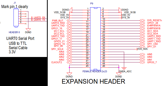
J1.1 is a normal digital ground, exactly the same as P9.1, P9.2 and others (from the official schematic):
bbb-j1.png
 
aragat said:
I found that the easiest way of working with BBB via serial terminal is to use sysutils/screen:
Code:
$ screen /dev/tty<your_device> 115200
Also, screen (by default) disables terminal's flow control by using Ctrl-S/Ctrl-Q, which will help you (but you can enable it with Ctrl-F).

Thank you Aragats for your suggestion, I just had the opportunity to make a small test and unfortunataly to me "screen" does not disable "Ctrl-s" out of the box. I tried Ctrl-f and also that does not disable it.
I will try to read better the super long man page and I will try again in the next days.

aragat said:
So in your case you better change your editor's settings to use something else to save.
This is not a good idea in my opinion.
When i am into Emacs (or mg) in think in Emacs-mode. It would be like swapping position of C and D in a piano keyboard ... a complete mess.

Unfortunately also "vi" does not behave in the way i am used to in Linux and OpenBSD, two days ago I was so desperate that I had to write a configuration file with "ed" !!!

The lesson for me was, don't blame dinos, they will come to rescue when everything else fails.

Bye
 
Do I need to do anything special to get serial output from BBB pins? Are Linux BBB overlays for serial working without modification?

I bought some db9/RS232 to TTL adapters with Max232 chip. What hardware are you guys using for serial from BBB?
https://www.dfrobot.com/product-196.html

I tried to connect into the BBB with many OS (OSX, Linux, OpenBSD and FreeBSD) mounting on the BBB also many OS (Debian/Linux, FreeBSD, OpenBSD) and my experience is, you only need to connect to the serial port (I use Adafruit adapter) and the set the speed to 115200 or 9600. It works, no need to put any DTO.

P.S. Adafruit adapter is annoying, if you find one with 6 pins buy that. With Adafruit all times I need to check my notes and read: Black wire --> pin1 (the one with bullet on side), Green -> pin 4, White -> pin 5.

Bye.
 
I just checked with my screen, and you're right, its parameters have no effect at all. Something has changed, since some time ago I needed the flow control and it didn't work by default in screen, that's why I learned how to enable/disable it. By the way, the correct shortcut is Ctrl-A F (I was wrong telling you it's Ctrl-F). The command line arguments don't work either:
Code:
screen /dev/ttyU8 115200,-ixon,-ixoff
 

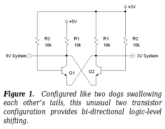
One day I was reading the Molloy book and I wanted to connect Arduino serial to BBB serial. I did not want to buy other misterious hardware so I built it my own, I had a lot of fun. Maybe you find it entertaining as well. I attach you the shcematics, JFF.

CAVEAT. I'am not an E.E, I take no resposibility, use it at your own risk;)

circuit1.png
 
Wow! You are a real electronician :)

I have to admit that transistors are sort of mysterious hardware to me even I know how they work.
I almost feel ashamed that I have to admit that I just use a 7406 or the like when I need a driver quickly, say for relays or leds... I even have still a few 1488/89 in my storage...
this is easier for me than using transistors... (so I can avoid to look again in the books about electronics basics :D)
 
Wow! You are a real electronician :)

I have to admit that transistors are sort of mysterious hardware to me even I know how they work.

Thank you Snurg but,
I must admit that was my first real circuit with transistors, and part of my objective in building it was "understand how use transistors";)

I also had a lot of troubles with transistors, even if i red many eletronics books chapters about them. One day I found Molloy book, which is super, i really reccomend it to you. There are pirate copies online, take a look, I am pretty sure you will recognize quality and you will decide to buy a paper copy. The BS270 is "voltage controlled", that is the key that simplifies all.
 
Well I tried my MAX3232 Serial-TTL Module with a fresh set of wires and same result. Ground pin on J1 would not work but Pin1 on P9 did.
So I looked at the MAX3232 datasheet and decided to try and use the BBB 5V pin for power and then J1 ground works for serial output..
I was worried putting 5V to the module. I had to try and figure out why one ground would work and one would not.
Something about the different voltages..
 
But you must not use 5V: it's harmful for your BBB, not for the serial adapter.
And this is because Vcc on the Max3232 determines the max TTL logic output level.
With 5V Vcc on the Max, its logic high output would be typically a diode drop lower, about 4.3V.
And this in turn would be well above the BBB's Vcc and probably kill it.
(though it might "work" for some unreliable esoteric reasons, like ungrounded rs-232 connections do sometimes due to circuit resistances and capacitances)

Alternatively you could use TTL level shifters, there are quite a few chips that do this very conveniently.
For this task I like DIL packaged 74LVC245, they are really convenient.
 
I found about the existence of level shifters only when I found that some Arduino stuff were for 5V and some for 3.3V and had to find out how to put these together...
Hardware things are hard to people who are math-agnostic like me :D
(This is the reason why I avoid using discrete transistors etc if possible)
 
Back
Top