The Robot Thread

I should have done my homework better on LiFePo4.

The batteries I got work fine but when I went looking at specs I noticed the deluxe LiPoFe4 from Powersonic have 3X the energy density.

I will not buy anymore motorcylcle batteries.... Only purpose built.

I can tell by tapping on the battery it is only half full of cells.... The top half is hollow. BMS is on very top.
 
I see USART in the pdf file for Nucleo. I need to look that up. Why are UARTS called that.

USART is an enhanced variant of UART, capable of both synchronous and asynchronous communication, and in modern microcontrollers it often replaces the simpler UART
 
I wanted to do a wrap up of my work to convert a Mobility Wheelchair into an Rover.

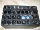
Pic. 1
Backbone is 2S 4P so I can change batteries without going down. An isolator circuit in between the two packs 4P would be ideal.
This will power my Flight Controller and Accessories. It also acts as a main battery holdown. Old rig used nylon straps.

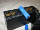
Pic. 2
24V Main Battery cutout switch with fusing. Very crude but works. Need to make a knob and pullcord for knife.

Pic. 3
RunCam Robin3 and DeeGoo-FPV GPS/Compass. Cracked it open and inside was M9N ublox.
 

Attachments

  • Pic3.JPG
    Pic3.JPG
    711.9 KB · Views: 67
  • Pic2.JPG
    Pic2.JPG
    1.1 MB · Views: 62
  • Pic1.JPG
    Pic1.JPG
    651 KB · Views: 59
resora
Sorry to bug you so much but I need your trusted advice. I want to monitor power.
I know my F405Wings have PDB/BEC and Monitoring. I am trying to avoid soldering those leads until I figure out wiring and connectors.
I have bulkhead/panel mount XT60 connectors that I want to use eventually.

I have bought a cheap power monitor device for benchtop use. Not much good with Rover on mission.
So I am looking at ways to monitor power. I know PIXHAWK had no integral power monitoring and they use a pigtail.
I like this approach but they seem to be using ADC and I don't know if I like that. I thought I would find i2c interface.

You can see from my Pic2 above that I have a nice gap for a shunt. I could do something there.
Opinions? Off the shelf items? What is good external power monitoring outside of the PDB/BEC found on some Flight Controllers.
 
ArduPilot already directly supports INA226, INA228, INA238, INA231, and INA260. It also supports multiple battery monitors at the same time, and each one can be assigned its own I²C address. ArduPilot also supports the INA3221, which is a three-channel I²C power monitor. However, if you are dealing with high currents, it would be better to use an INA228 or INA238.
 
I am going to buy a few of these to test. Three addresses to use. I will drill addition holes for one of these in the gap of my power switch.

I also want to use a cheapo INA219 to monitor low voltage from LiPo to Flight Controller.

With the Matek having pass through connectors, connecting the second i2c monitor should be easy and minimal extra wiring.
Exactly why I wanted i2c. Daiseychaining.
 
I don't see MAUCH anywhere on ebay.
For Generic i2c modules for low voltage on Flight Controller I got some generic ones due to your input about ina226 chip:
5 pack of sensors for 21 bucks.
No jumpers/pads so they will go end of that daiseychain.

Anybody have recommendations on 'Temporary Jumper" to change i2c address on boards?
Also related: Nucleo Boards have a bunch of solder pad options that can be changed.
Bubble gum and silverdust?
JB Weld with tiny wire?
When I was afraid of using soldering iron on micro leads I tried some silver conductive glue. It was a mess and killed it. Should have made a mask.

Soldering Address is sorta permanent. I would like to test because end unit may not be selactable address.

Very small pitch:
 

Attachments

  • pads.jpg
    pads.jpg
    22.1 KB · Views: 48
I have a very welcome Amazon delivery. Two ESC 70A Burst to 200A. USB Jack for tuning to suit motors with an application..
Flysky FESC6.7
 

Attachments

  • FS-3.JPG
    FS-3.JPG
    1.3 MB · Views: 60
  • FS-2.JPG
    FS-2.JPG
    1.2 MB · Views: 66
  • FS-1.JPG
    FS-1.JPG
    1.2 MB · Views: 61
Need to make a knob and pullcord for knife.
The nice thing about posting my pictures here is that I get ideas.
Instead of pullcord for power cutoff knife I will mount a handle that faces left. Away from circuit. Rotate left to de-energize.
Brilliant idea. I have no good mounting option for a external pullcord anyway. The machines Covers are only velcro hold-down anyway. Tearaway.
 
Soldering Address is sorta permanent. I would like to test because end unit may not be selactable address.

Very small pitch:
you have a "zero resistance" tweezers, you can use it as a jumper for the test
You can wind the wires for the test and attach them with non-conductive tape to the pads
Also use pogo pins
 
I am firing up my rover project.. All parts are installed and doing fit&finish. Blocks under it to get it off the ground.
Tested motors with straight 24VDC Lead Acid Main Battery and that was a go.
Running CoreSolo F405-Wing from 18650 battery pack.
Soldering went OK for first one. Will get better at it. Learned alot.

Need to plumb GPS wires, Camera Wires and i2c for ina226 module & Matek i2c BM..
INA226 module is inline right now for flight controller and monitor 18650 use..
Just need to get i2c expander placed somewhere.

Adding an external port to my rover for my USB connection for the flight controller.
The 20 foot umbilical cord is functioning with MissionPlanner on laptop using FreeBSD.

I was worried that my ESC are bad. I tied the main batteries to the ESC with no RC-Line attached.
Red light came on and 2 seconds later went out.
Worried I yank the plug.
Thinking maybe issue with Lead Acid I gave LifePo4 batteries a shot on the other ESC controller..
Same thing. Solid Red LED for a few seconds then it goes out.
I hit the ArduPilot manual and see that I may need to calibrate ESC.
Before that I need to setup mode for Servos. I don't see SKID STEER. There is Ground Steer.
I think I have cleared the hardware hurdle. Now on to setup of my ArduRover.

Thanks resora for all the help.

I might add a RockPi4 later for additional control onboard. Atheros WirelessAP and more GPIO. Maybe I will use that as my ELRS.
I have UART1 set to RC_IN and I hope that my DSM Spektrum gear works with that.
 
I can't help but to notice that HUD is showing Bat1 without a working INA226.
So that was a waste purchase.
Very nice HUD feature showing 15.04v 0.8 A 26% from flight controller onboard PDB.
My batteries started off at 16V with multimeter. Been running 3-4 hours.
Nice how it is estimating runtime.
0.8A seems too high of usage. Might need to verify those numbers.
usbconfig was showing 100mA with no batteries in use.

I want to do a 24hour burn to see duration of flight controller 18650 battery pack.
4 cells x 4.1v full charge and should cut out around 3V or 12V for the four.
16V max to 12V cutout is my anticipated range.
 
The 18650 pack has been powering my fight computer for days on end. It is down to 14.5V or less now. Very respectable. probably around the 80-100mA mark.

Setting up ArduPilot for Pre-Flight Checks took me several days. Calibrating everything. I chose not to override anything. Had to change OSD2_TYPE

Once I could finally "ARM" my Rover I could still not get my motors to spin from the "Test Motors" Panel.
I was using SoloGood F405 Wing and it did not have a firmware for Ardupilot.
So I decided to solder up more stuff and completed JHEMCU F405WING with an official firmware.
I think RC_IN was not working right on Sologood for UART1 and I tried on UART6.
Could not see the bars move to calibrate Radio Transmitter. Like its not seeing RC line.
So I switched to test other controllers. JHEMCU F405 is the nicest so far. That one is better building than the Matek F405 they copied.
Mostly because they used JST connectors instead of 2.54mm/p headers.

The wiring to Power Distro Board worried me with thicker wire. So I added a makeshift strain relief like I did with the SoloGood board.
I mounted the flight controller on a SKID so I can change them out..

Included is a picture of my rover in progress.
 

Attachments

  • rover1.jpg
    rover1.jpg
    1.1 MB · Views: 42
  • jhemcu1.jpg
    jhemcu1.jpg
    1 MB · Views: 35
I am getting close... There will be not eureka moment here as I was expecting. Just a gradual seepage of life for my Rover.

ArduPilot has Motors Spinning. 100% " Test Motor C" and "Test Motor D" works after increasing throttle. Dead Zone needed adjusting in Test Motors.

So many things need calibrating and adjusting. It has been maddening learning how to ARM the flight controller. Must be 8 items to clear for "Pre-Flight" on new board.
I chose to keep using MissionPlanner and finally found a good tutorial. Heck first 20 seconds solved it.
I just needed to see wheels spin via flight controller. To preserve my sanity.

View: https://www.youtube.com/watch?v=5ySmzuqE_bg


Radio Problems.
For some reason my Spektrum SR3000 receiver is not co-operating. I see no green bars in calibration. Error "Bad channel 1 input". So I have been fighting that.
Glad I switched flight controllers to see the same error on both was OK.
So I have tried RC_IN as UART1 with half-duplex and 115200. That seems to be the correct settings from my reading. I tried changing speed. Changing port.
When I look at parameters there seem to be no options for DSM. Its all auto-detect.
RC_Protocols is 1 (auto)
RC_OPTIONS is 32
Tested changing RCMAP to different settings.

Servos setup as RightThrottle=S1 and Left Throttle=S3 and that tested correct with "Motor C" and "Motor D" running as directed.
Tried running receiver from separate battery. Increased voltage to 8V.
Transmitter Pairs fine and I see Green LED on Receiver when I turn on transmitter.
It is an RC_IN problem. My guess.

I bought another receiver to try. Transmitter is fine and I have manually controlled my motors via RC Transmitter. Lots of testing trying to diagnose.
Reading some I see a command line program to probe dsm status.
I have not logged into the controller via command line option yet.

I just wonder if spending $30 on SR210 receiver was dumb. I have a feeling the DSM2 protocol works. I will find out.
The Spektrum DX2.0 RC transmitter may support DSM2. I hope so. I would like to stick with the RC Transmitter I have.
I almost bought the Orange DSMX receiver. It should work with my gear. I figured I would stick with Spektrum gear to test DSM2.
 
I think the problem is receiver needs to have 4 Channels minimum.
RC_MAP seems to suggest that these are needed,

RC_MAP_PITCH
RC_MAP_ROLL
RC_MAP_THROTTLE
RC_MAP_YAW


My RC Transmitter has 2 Channels and the receiver has 3 outputs. Steering, Throttle and AUX. One Marked BAT/TEL
I think this is the cause of my error.
"Bad channel one input. error"

I messed with RC_MAP and set Throttle=1 and Yaw=2 no good. Set RC_PROTOCOLS for DMS bitmask 32
I wish I had an O-scope to put inline to see signal.
Changed RC_OPTIONS to 48

For my project and most rovers/boats 2 Channels should be enough. I just don't know what is wrong. I changed 3 Pin wires to another set.
I looked at the build files I did not expressly did not see RC_PROTOCOL DSM even though manual shows DSM. It may be under PPM.


Probably something I am doing wrong. I tried to set the un-needed channels to Zero and that does not work.
PITCH and ROLL are not needed.. Only needed are Throttle and Steering//YAW//Rudder
Does that sound right? Why is rover trying to use pitch and roll?

MODE_CH is trying to use Channel 8. That may need looking at. I don't have a channel 8 on RC Transmitter. Rover is supposed to use CH_5 I read.

Also tried the SBUS pin for signal to Receiver.. No luck. Tried TX PIN. No Luck. TX Pin is where it supposed to be in my reading. INAV had a nice diagram.

I am upgrading my gear. It is from 2010. I would like to stay with Spektrum. Maybe DX4C because it has 4 channels.
My receiver has Throttle, Steering, AUX and BATT/TEL
I am using the BATT/TEL pins to connect to TX lines of UART1.
Is that correct?
Some Spektrum receivers are marked BAT/DATA I noticed.

Last night I bought some Spektrum gear. Used controllers and new Spektrum AR620 receiver. I am upgrading everything to DSM2+.

Wanted a generic GamePad style RC Controller. ParkZone/HobbyZone and other similar brands. DSM2

I really could not decide on second one. I went with traditional plane controller DX4e.
It was the cheapest 4 channel controller I could find. I am not sure the stick centers on gamepad style above. So I got one that does.
I wanted the DX6C/DX6R but I will get that later. Replace my Car style controller with something newer.

Since I have multiple projects a few transmitters will be needed.

I could try setting up a track in preparation for field tests. Waiting on parts. Wait for RC controllers to arrive. Gave up on DSM1. Obsolete.
The precision of the GPS is amazing with GPS lock.
 
I read that Spektrum receivers like lower working voltage so I tried with 4V and no help.

I see you had me turn on the bitmask for "Log RC Input Bytes" I need to figure out how to read the log being it is binary.
I want to see what is transpiring.
In "Message Pane" on bootup all I see it RCOut no mention of RC_IN

With this Spektrum Receiver I bought the DATA signal line goes to UART?
I assume DATA line to UART1 TX on flight controller?
Where do I plug in? Manual is useless.
 
Back
Top