Raspberry PI CM4 and RTC

Hi,

I have a device using Pi compute module 4, which seems to have a real time clock
(documentation shows pcf85063a). I wonder if there are any means to get it
working with FreeBSD ? I spent yesterday trying to figure this out and adding
things like

Code:
dtparam=i2c_vc=on
dtoverlay=i2c-rtc,pcf85063a,i2c_csi_dsi

to config.txt does not really seem to do anything.

There is i2c controller detected in boot:
# dmesg|grep iic
iichb0: <BCM2708/2835 BSC controller> mem 0x7e205000-0x7e2051ff irq 19 on simplebus0
iicbus0: <OFW I2C bus> on iichb0
iic0: <I2C generic I/O> on iicbus0

But scanning the bus doesn't find anything:
# i2c -v -s
dev: /dev/iic0, addr: 0x748a3ff8, r/w: r, offset: 0x00, width: 8, count: 1
Hardware may not support START/STOP scanning; trying less-reliable read method.
<Nothing Found>

Any ideas anyone ?
 
pcf85063a is not supported use without trailing a.
anyway it should test with i2c even without kernel support
device address should be 0x51
 
Here is what you want to do.
Install port for raspberry-pi firmware. This will bring you pre-compiled DTB overlays that you copy to your /boot/dtb/overlays/ directory.

Then when you add them to config.txt they will work.

You need these overlay:
i2c-rtc
i2c0 (Or appropriate bus the device is on as found with i2c scan.)
pcf85063a
I don't think this setting will work because we have no driver for that RTC.
 
Here is what you want to do.
Install port for raspberry-pi firmware. This will bring you pre-compiled DTB overlays that you copy to your /boot/dtb/overlays/ directory.

Then when you add them to config.txt they will work.

You need these overlay:
i2c-rtc
i2c0 (Or appropriate bus the device is on as found with i2c scan.)

I don't think this setting will work because we have no driver for that RTC.
pcf85063 has a driver and seems the same
you just modify the dts or something and rebuild it (or the source code)
 
Indeed RTC drivers seem pretty adaptive. I have used other driver with success.

The thing with i2c bus is number can change like drive letters do. So if doing tutorial try all buses.

So to start with you might want to enable all i2c bus overlays. i2c0,i2c1,i2c2 ect... to do bus scanning.

Warning you will see system periphery like HDMI with i2c scan.

Having the address covacat provided is most useful. You could see other system devices in your scans. My RTC modules use 0x68 by default.
 
I did some experiments with i2c scanning. I enabled all i2c busses by putting this into
config.txt:
Code:
dtoverlay=i2c0
dtoverlay=i2c1
dtoverlay=i2c2
dtoverlay=i2c3
dtoverlay=i2c4
dtoverlay=i2c5
dtoverlay=i2c6

After that, dmesg shows actually six busses:

Code:
iichb0: <BCM2708/2835 BSC controller> mem 0x7e205000-0x7e2051ff irq 19 on simplebus0
iichb1: <BCM2708/2835 BSC controller> mem 0x7e804000-0x7e804fff irq 27 on simplebus0
iichb2: <BCM2708/2835 BSC controller> mem 0x7e205600-0x7e2057ff irq 50 on simplebus0
iichb3: <BCM2708/2835 BSC controller> mem 0x7e205800-0x7e2059ff irq 51 on simplebus0
iichb4: <BCM2708/2835 BSC controller> mem 0x7e205a00-0x7e205bff irq 52 on simplebus0
iichb5: <BCM2708/2835 BSC controller> mem 0x7e205c00-0x7e205dff irq 53 on simplebus0
iicbus0: <OFW I2C bus> on iichb0
iic0: <I2C generic I/O> on iicbus0
iicbus1: <OFW I2C bus> on iichb1
iic1: <I2C generic I/O> on iicbus1
iicbus2: <OFW I2C bus> on iichb2
iic2: <I2C generic I/O> on iicbus2
iicbus3: <OFW I2C bus> on iichb3
iic3: <I2C generic I/O> on iicbus3
iicbus4: <OFW I2C bus> on iichb4
iic4: <I2C generic I/O> on iicbus4
iicbus5: <OFW I2C bus> on iichb5
iic5: <I2C generic I/O> on iicbus5

But scanning (i2c -f /dev/iicN -s -v) doesn't find anything:
dev: /dev/iic0, addr: 0x57f08a0, r/w: r, offset: 0x00, width: 8, count: 1
Hardware may not support START/STOP scanning; trying less-reliable read method.
<Nothing Found>
dev: /dev/iic1, addr: 0x6b93a118, r/w: r, offset: 0x00, width: 8, count: 1
Hardware may not support START/STOP scanning; trying less-reliable read method.
<Nothing Found>
dev: /dev/iic2, addr: 0x2b73cdf0, r/w: r, offset: 0x00, width: 8, count: 1
Hardware may not support START/STOP scanning; trying less-reliable read method.
<Nothing Found>
dev: /dev/iic3, addr: 0x373ae8b8, r/w: r, offset: 0x00, width: 8, count: 1
Hardware may not support START/STOP scanning; trying less-reliable read method.
<Nothing Found>
dev: /dev/iic4, addr: 0x243f3d0, r/w: r, offset: 0x00, width: 8, count: 1
Hardware may not support START/STOP scanning; trying less-reliable read method.
<Nothing Found>
dev: /dev/iic5, addr: 0x2a96dfc0, r/w: r, offset: 0x00, width: 8, count: 1
Hardware may not support START/STOP scanning; trying less-reliable read method.

I got worried about if there is any RTC at all and tried with Raspberry Pi OS. With

Code:
dtparam=i2c_vc=on
dtoverlay=i2c-rtc,pcf85063a,i2c_csi_dsi

in config.txt it detects the RTC and uses it. So the chip is actually there (this doesn't help me otherwise,
since all our stuff is FreeBSD-based). I wonder why it is not detected with FreeBSD.
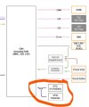
I'm attaching a picture from documentation (it's OnLogic FR201), which shows that the RTC should be on i2c0.

Any further ideas about this are welcome.
 

Attachments

  • cm4_fr201.jpg
    cm4_fr201.jpg
    35.2 KB · Views: 189
Forgot boot log from Raspbian, which interestingly shows i2c 10:

Code:
[    1.326192] i2c i2c-22: Added multiplexed i2c bus 0
[    1.331694] i2c i2c-22: Added multiplexed i2c bus 10
[    1.355923] brcmstb-i2c fef04500.i2c:  @97500hz registered in polling mode
[    1.361069] brcmstb-i2c fef09500.i2c:  @97500hz registered in polling mode
[    1.407683] rtc-pcf85063 10-0051: registered as rtc0
[    1.410096] rtc-pcf85063 10-0051: setting system clock to 2025-06-04T12:37:09 UTC (1749040629)

Looks like the rtc chip is on bus 10, address 51. But there is no overlay activated for i2c10 so I don't really understand
how it gets created.
 
So maybe you need to look at the dtb you are using on FreeBSD. Maybe it is not presenting the devices properly.

What u-boot and dtb are you using? Where did it come from?
 
So maybe you need to look at the dtb you are using on FreeBSD. Maybe it is not presenting the devices properly.

What u-boot and dtb are you using? Where did it come from?
Stock FreeBSD 14.2 and latest rpi-firmware package.
 
The only reason I brought that up is I had trouble with the Rock CM3 and u-boot and needed a different build than the other Rock3 boards. IO was piped different.

I still wonder if you have the right combination of overlay for i2c.

This is the u-boot for the above defconfig.
sysutils/u-boot-rpi-arm64
So you can pkg install it or if you build from ports you might find a DTB file is generated for CM4. You have to dig through the u-boot work directory and find the DTB('s) it builds.

Download ports tree.
cd /usr/ports/sysutils/u-boot-rpi-arm64
make install

You can save ports building for dependencies with this beforehand:
make build-depends-list | cut -c 12- | xargs pkg install -A -y
This will keep your system on packages except for this u-boot build.
Build should take no longer than 30 minutes.

Then when complete you rummage through the build directory for DTB
find /usr/ports/sysutils/u-boot-rpi-arm64/work -name "*.dtb"
 
Indeed when you build the port you get all the dtb's built:


/usr/ports/sysutils/u-boot-rpi-arm64/work/u-boot-2025.07-rc2/arch/arm/dts/bcm2835-rpi-a.dtb
/usr/ports/sysutils/u-boot-rpi-arm64/work/u-boot-2025.07-rc2/arch/arm/dts/bcm2835-rpi-a-plus.dtb
/usr/ports/sysutils/u-boot-rpi-arm64/work/u-boot-2025.07-rc2/arch/arm/dts/bcm2835-rpi-b.dtb
/usr/ports/sysutils/u-boot-rpi-arm64/work/u-boot-2025.07-rc2/arch/arm/dts/bcm2835-rpi-b-plus.dtb
/usr/ports/sysutils/u-boot-rpi-arm64/work/u-boot-2025.07-rc2/arch/arm/dts/bcm2835-rpi-b-rev2.dtb
/usr/ports/sysutils/u-boot-rpi-arm64/work/u-boot-2025.07-rc2/arch/arm/dts/bcm2835-rpi-cm1-io1.dtb
/usr/ports/sysutils/u-boot-rpi-arm64/work/u-boot-2025.07-rc2/arch/arm/dts/bcm2835-rpi-zero.dtb
/usr/ports/sysutils/u-boot-rpi-arm64/work/u-boot-2025.07-rc2/arch/arm/dts/bcm2835-rpi-zero-w.dtb
/usr/ports/sysutils/u-boot-rpi-arm64/work/u-boot-2025.07-rc2/arch/arm/dts/bcm2836-rpi-2-b.dtb
/usr/ports/sysutils/u-boot-rpi-arm64/work/u-boot-2025.07-rc2/arch/arm/dts/bcm2837-rpi-3-a-plus.dtb
/usr/ports/sysutils/u-boot-rpi-arm64/work/u-boot-2025.07-rc2/arch/arm/dts/bcm2837-rpi-3-b.dtb
/usr/ports/sysutils/u-boot-rpi-arm64/work/u-boot-2025.07-rc2/arch/arm/dts/bcm2837-rpi-3-b-plus.dtb
/usr/ports/sysutils/u-boot-rpi-arm64/work/u-boot-2025.07-rc2/arch/arm/dts/bcm2837-rpi-cm3-io3.dtb
/usr/ports/sysutils/u-boot-rpi-arm64/work/u-boot-2025.07-rc2/arch/arm/dts/bcm2711-rpi-4-b.dtb
/usr/ports/sysutils/u-boot-rpi-arm64/work/u-boot-2025.07-rc2/dts/dt.dtb
/usr/ports/sysutils/u-boot-rpi-arm64/work/u-boot-2025.07-rc2/u-boot.dtb

It does not seem like a CM4 is built..... Maybe it does use stock rpi4 u-boot. I dunno.

Looking on the internets it should be named this:
bcm2711-rpi-cm4.dtb

I always feel the correct DTB is a baseline. I really don't understand why u-boot doesn't build this dtb.
 
If you install the sysutils/rpi-firmware package it installs the necessary files in /usr/local/share/rpi-firmare/.

There are two DTB an I am not sure the difference.

bcm2711-rpi-cm4.dtb
bcm2711-rpi-cm4-io.dtb

The ports instructions mention this:
The rpi-firmware package installs files to /usr/local/share/rpi-firmware/.
To update the firmware used to boot, copy these files to /boot/msdos,
and then copy the appropriate config_<type>.txt file to
/boot/msdos/config.txt.

For example, on a Raspberry Pi 4 Model B,

cp -pr /usr/local/share/rpi-firmware/* /boot/msdos/
cp /boot/msdos/config_rpi4.txt /boot/msdos/config.txt

I don't know that I would copy everything from rpi-firmware like that. I usually copy over things I need.
 
It does not seem like a CM4 is built..... Maybe it does use stock rpi4 u-boot. I dunno.

Looking on the internets it should be named this:
bcm2711-rpi-cm4.dtb

The dtb files for cm4 are part of rpi-firmware.

Code:
ls /usr/local/share/rpi-firmware/*cm4*
/usr/local/share/rpi-firmware/bcm2711-rpi-cm4-io.dtb
/usr/local/share/rpi-firmware/bcm2711-rpi-cm4.dtb
 
The source code has good documentation for the overlays.


It looks like you have the correct combination.
dtoverlay=i2c-rtc,pcf85063

I found this factoid about the overlays interesting:
i2c0 Choose the I2C0 bus on GPIOs 0&1

i2c_csi_dsi Choose the I2C0 bus on GPIOs 44&45
So the i2c_csi_dsi overlay should shift i2c0 to the MIPI/DSI connector instead of GPIO pins. I don't think you want that.
 
I am pretty sure you need this setting too:

dtparam=i2c_arm=on

I seem to remember that setting from my RPi3 boards.
I did not realize this is an ONLOGIC baseboard.
So is it clone of CM4 baseboard?
With M.2 slots you might need the bcm2711-rpi-cm4 -io.dtb file.

Have you looked at the dtbs and bootloader provided by OnLogic and their Linux stuff?
Scrape the dtb from there and look at this too:
If you are encountering general issues with your FR200 series system, such as the Real-Time-Clock (RTC) disconnecting, various ports not being detected, or features not working as expected, make sure you’re using the OnLogic provided config.txt and usercfg.txt files. These add additional functionality to the system, and allow the Raspberry Pi CM4 module to properly interface with the OnLogic designed FR200 series daughterboards. You can download the files from the Manual and Downloads section above.
 
Here are two settings I pulled from OnLogic BookWorm_64bit.zip and the config.txt included. The rest seem irrelevant.

You want to try these settings in your config.txt.
# Config settings specific to arm64
arm_64bit=1
dtoverlay=dwc2
DesignWare Controller(dwc2) might be used for M.2 slots. Not Related to I2C.


The other setting that is not relevant to RTC but it is I2C. There is ADC on I2c5:
dtoverlay=i2c5,pins_12_13=on,baudrate=40000

And now from userconfig.txt settings I think you will need. These will go in config.txt too.

dtparam=i2c_arm=on

[all]
dtoverlay=i2c1,pins_44_45=on
dtoverlay=i2c-rtc,pcf85063a=on
You may need to try pcf85063 instead here.
 
After putting this to config.txt
Code:
dtoverlay=i2c1,pins_44_45=on
dtoverlay=i2c-rtc,pcf85063=on

things look better during boot:
Code:
pcf850630: <NXP pcf85063 Real Time Clock> at addr 0xa2 on iicbus0
pcf850630: registered as a time-of-day clock, resolution 1.000000s

But later in boot there is this:

Code:
Error reading time-of-day clock (35), system time will not be set accurately

However, this looks promising now.
This looks that FreeBSD detects RTC device via device tree definition but it can't talk to RTC later. So still i2c setting isn't correct.

I don't have CM4 but https://forums.raspberrypi.com/viewtopic.php?t=293632&p=1774139 says that GPIO44&45 are used for i2c. How do you see the port function on freebsd?
Code:
sysctl dev.gpio.0.pin.44.function
sysctl dev.gpio.0.pin.45.function
They should be alt1.
Do you see alt1 on GPIO44 and 45?
 
Nope.
Code:
% sysctl dev.gpio.0.pin.44
dev.gpio.0.pin.44.function: input
% sysctl dev.gpio.0.pin.45
dev.gpio.0.pin.45.function: input

Tried changing that with sysctl, but i2c scan still doesn't find anything.
 
It looks like you are connecting to the correct i2c bus now.
Naming sure is a strange convention here. The diagram clearly shows i2c0 for RTC.
It seems sometimes i2c bus starts at address 0 and sometimes it starts at 1.
If you don't activate all the i2c buses then what might be i2c5 in instructions could be i2c2 on the OS level.

I wonder if you are hitting the differences between the (a) model of this RTC if the muxing is correct.

Looking at the source the dwc2 controller is for USB.
 
It really helps to have a serial console to see FreeBSD 'pre-boot' messages about overlays. See if they applied cleanly.

Also ofwdump -a shows nodes once booted.
 
Back
Top