Orange Pi Zero / how to access internal flash device

This is kind of a final problem while trying to have a Orange Pi Zero to do disk-less pxe-boot from a server, so I can have a small cluster of Zero's running the same system tree without local storage required.
To do that, the internal flash volume must be overwritten with the bin file that comes with the u-boot-orangepi-zero port. I currently need Armbian for it, which I don't like.
But I can't find a FreeBSD solution. In the GENERIC -SD armv7 release, I can only see the kernel referring to mmc0 but there's no device. Not sure what I have to do for this.

Do I need SPI support with option spidev in de kernel configuration? I tried it but didn't notice any changes.
The /boot/dtb/overlays dir contains various dtbo files, including sun8i-h3-spi0.dtbo that can be loaded in /boot/loader.conf but they all say "not compatible". Ofcourse I tried AI questioning, but they all seem to assume that the 2 devices just exist: the internal storage device and the board sd-card device.

Current dmesg about the mmc0 device:
Code:
mmc0: <MMC/SD bus> on aw_mmc1
mmc0: No compatible cards found on bus
 
Update: I tried the GENERIC-MMCCAM kernel version. This results in a /dev/sdda0 device, which is the same as the sd-card mmcsd0.

The mmc0 device now shows different info. No "carrd not found" but it still isn't accessible by a /dev entry.
Code:
aw_mmc0: <Allwinner Integrated MMC/SD controller> mem 0x1c0f000-0x1c0ffff irq 10 on simplebus0
 
The SPI device will show up under /dev/flash/spi0 or similar.

Edit:WRONG
You can treat it like an ordinary block device. dd zero and dd write image to it.
 
Last edited:
The SPI device will show up under /dev/flash/spi0 or similar.

You can treat it like an ordinary block device. dd zero and dd write image to it.
Not on a GENERIC-SD system. At least, the directory doesn't exist and can't be created.
 
At least, the directory doesn't exist and can't be created.

Does u-boot see a SPI device with their sf command?

Are you able to get to the U-Boot command line with a serial console?

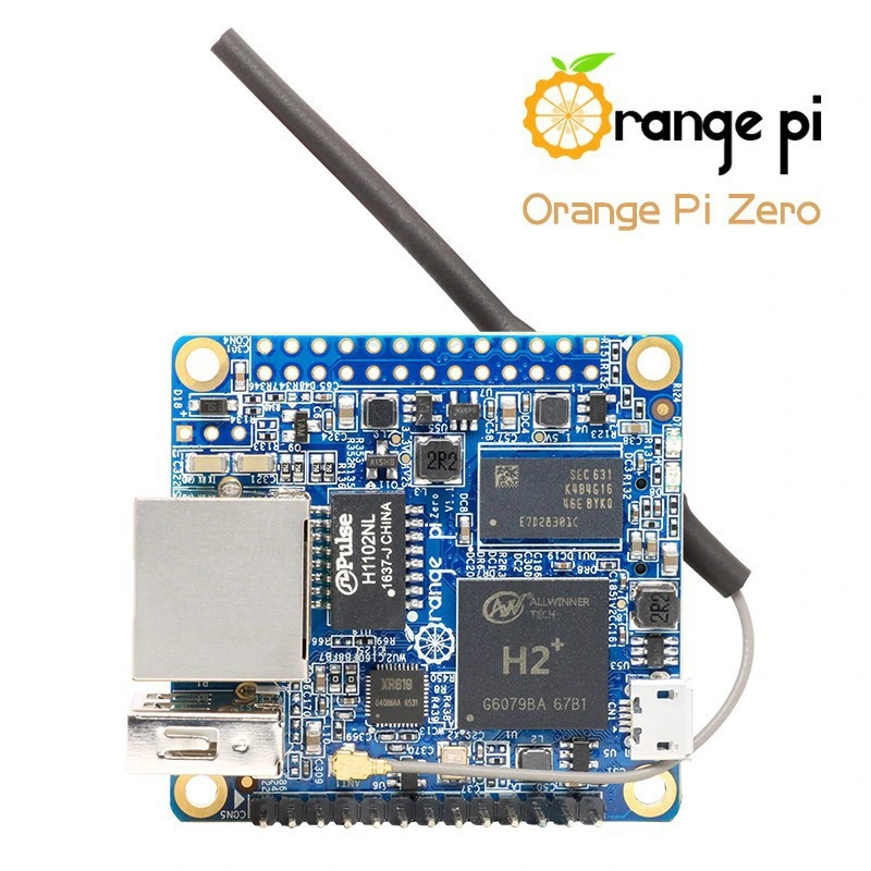
Have you verified that your device actually has an SPI chip on the underside?

Lastly use Armbian to your advantage.
 
Last edited:
I already wrote an image to it using the recommended Armbian installation for this board. The SPI device exists and works. After making a working tftp/dhcp/nfs server, writing a bootloader to the device using FreeBSD is the last thing I need to boot a cluster of these things without SD-cards.
Now waiting on a kernel build before I can try to get in the loader prompt. I didn't configure anything on the u-boot release for this system. It might be missing something...
 
I didn't configure anything on the u-boot release for this system. It might be missing something...
What I have found is that unpatched Uboot will work with FreeBSD but you need to use a EFI OS setup for it to find the loader. Uboot don't understand UFS without patching. EFI gets around that.
I am not sure about a SPI u-boot.
 
What I have found is that unpatched Uboot will work with FreeBSD but you need to use a EFI OS setup for it to find the loader. Uboot don't understand UFS without patching. EFI gets around that.
I am not sure about a SPI u-boot.
U-boot does work with FreeBSD. In Armbian, I wrote FreeBSD's u-boot bin file to the SPI storage. If boots FreeBSD from Sd-card or remote server with no problems. Access to the device in FreeBSD is really all I need. I believe it's 16MB. Besides disk-less booting from it, it's also useful to store a few small files.
I'm not entirely sure, but I think the SD-slot has override on anything. If there's a card, it will try to boot it. I don't think you can 'brick' these boards.

I believe I have to generate a dtbo file from a dts file, but I'm not sure which file to use and what it's SPI entry should look like.
 
Here is what I would recommend.
Build uboot from ports.
/usr/ports/sysutils/u-boot-orangepi-zero/

After make look in u-boot root build dir for:
u-boot-sunxi-with-spl.bin

I believe it's 16MB.
Spec sheet says 2MB

 
Here is what I would recommend.
Build uboot from ports.
/usr/ports/sysutils/u-boot-orangepi-zero/

After make look in u-boot root build dir for:
u-boot-sunxi-with-spl.bin


Spec sheet says 2MB

I did all of that, including working through that Hackaday page. Later, I built the ports version of u-boot, and wrote the bin file to the SPI storage using Armbian because I can't access the device in FreeBSD. It all works except direct access to this internal storage from the FreeBSD CLI. This problem is what I want to get rid of, so I can make a FreeBSD-only howto for building a pxe-booting cluster of these boards.

There's still 1 other thing I want to try out: using the RF coaxial display output and get it working on a TV in a reasonable graphics resolution. A series of analogue display wires is actually quite interesting. I haven't seen people do anything with it but it can be combined to a giant output framebuffer, or used for alternative 1-wire communication.
 
Update: After a lot of searching, I found out that I probably have to generate a new dtb (device tree blob) file because the original FreeBSD 13.2 source file /src/sys/contrib/device-tree/src/arm/sun8i-h2-plus-orangepi-zero.dts has the spi entry set on "disabled". I changed it to "okay" like the other entries.

The file should be compiled using the dtc port with the command
Code:
dtc -I dts -O dtb -o ./sun8i-h2-plus-orangepi-zero.dtb ./sun8i-h2-plus-orangepi-zero.dts

This should generate new output dtb file, but we get a multiple error related to a variable. (Or it's a syntax error for real, but I don't think so)
Code:
Error at ./sun8i-h2-plus-orangepi-zero.dts:73:24: Expected numbers in array of cells
                        gpios = <&r_pio 0 10 GPIO_ACTIVE_HIGH>;
                                             ^
Error at ./sun8i-h2-plus-orangepi-zero.dts:73:24: Expected ; at end of property
                        gpios = <&r_pio 0 10 GPIO_ACTIVE_HIGH>;
                                             ^
Error at ./sun8i-h2-plus-orangepi-zero.dts:73:24: Failed to find root node /.
                        gpios = <&r_pio 0 10 GPIO_ACTIVE_HIGH>;
                                             ^

Do I need GPIO_ACTIVE_HIGH defined somewhere somehow? What even is the format of this dts text? It looks like C but not exactly...
If I comment out the block at this particular error line number, the error shifts to the next reference to GPIO_ACTIVE_HIGH. That goes on until there's barely anything left of the file, resulting in a unuseable dtb file while showing on screen:
Code:
Unable to merge node: cpu0
Unable to merge node: ehci0
Unable to merge node: ehci1
Unable to merge node: emac
Unable to merge node: mmc0
Unable to merge node: mmc1
Unable to merge node: ohci0
Unable to merge node: ohci1
Unable to merge node: spi0
Unable to merge node: uart0
Unable to merge node: uart1
Unable to merge node: uart2
Unable to merge node: usb_otg
Unable to merge node: usbphy
 
OK what I recommend is do not recompile DTS but make a DTB overlay for the SPI device 'Okay' setting.
Overlays override default dtb settings.

But to the point to compile this DTS do you see any "Includes" at the top???
If so you must point DT Compiler to the /include/ directory location in source tree.

DT-Bindings is commonly 'included' and needed for compiling.

Usually dtc -i /usr/src/sys/contrib/device-tree/ is what you need to include this directory.
The file has include commands:
Code:
/dts-v1/;                                                                                                                             
#include "sun8i-h3.dtsi"                                                                                                              
#include "sunxi-common-regulators.dtsi"                                                                                               
                                                                                                                                      
#include <dt-bindings/gpio/gpio.h>                                                                                                    
#include <dt-bindings/input/input.h>

These files exist in /usr/src/sys/contrib/device-tree/src/arm
Referring with -i to /usr/src/sys/contrib/device-tree or /usr/src/sys/contrib/device-tree/src/arm doesn't make a difference.

I also checked this file in the FreeBSD 12.3 source. It's identical.

An overlay file could be possible but what do I need? I have the dir /boot/dtb/overlays which contains .dtbo binary files.
 
For overlay it helps to look at examples.
Armbian has a good AllWinner repository:

I am pretty sure SPI is considered NOR
Why this is disabling I dunno.

Best to just use your existing DTS patch but turn it into an overlay.
Use this Linux stuff for rough guidance for layout needed.
 
do it like
cpp -I /sys/contrib/device-tree/include/ -x assembler-with-cpp /sys/contrib/device-tree/src/arm/sun8i-h2-plus-orangepi-zero.dts |dtc -I dts > my-new-dtb.dtb
or decompile the original dtb with dtc -I dtb, edit the resulting dts and compile that

just use your patched dts in the cpp line, not the original one like in my example
I decompiled /boot/dtb/sun8i-h2-plus-orangepi-zero.dtb that comes with the 13.2 GENERIC-SD release.
The output is very long and totally different than the dts file with the same name in the 13.2 source, that I was trying.

Next, I put in /boot/loader.conf: fdt_overlays="sun8i-h2-plus-orangepi-zero.dtb"
This results in an error at boot:
Code:
applying DTB overlay '/boot/dtb/sun8i-h2-plus-orangepi-zero.dtb'
failed to apply overlay: FDT_ERR_BADOVERLAY
---<<BOOT>>---

This happens both with the unchanged text and with spi 0 and spi 1 set to "okay".
So, a decompiled/recompiled dtb doesn't result in a identical file as the original, which I find strange since there are no different versions of this board, as far as I know.

Am I using the right option here to load this dtb file? It looks like it's assumed to be a overlay. I found other loader.conf options that seem to have no effect at all. dtparams, fdtfile, fdt_overlays, fdt_overlay... Is there any resource with the full option list for ARM SBC's?
 
Next, I put in /boot/loader.conf: fdt_overlays="sun8i-h2-plus-orangepi-zero.dtb"
This results in an error at boot:
Why? You are putting the boards DTB file in Overlays? That is wrong.
Decompile, Edit (change disabled to okay), Recompile.
That is all you need to do. (Reboot for it to take effect if done on same machine.)
Down and dirty.
 
Ok, removed that line and copied the compiled dtb file over the existing one in /boot/dtb
This changes nothing. Still having these boot-messages:
Code:
mmc0: <MMC/SD bus> on aw_mmc1                                                                                                      
mmc0: No compatible cards found on bus                                                                                            
aw_mmc1: Spurious interrupt - no active request, rint: 0x00000004                                                                  
mmc1: <MMC/SD bus> on aw_mmc0

Not sure if I need mmc0, though but it is the target device. I'm expecting a spi0.0 device that can be written to using flashrom. The device naming logic seems a bit weird to me. While mmc0 is the internal flash volume, mmcsd0 is the sd-card reader, which is on mmc1, I suppose.
 
I'm expecting a spi0.0 device that can be written to using flashrom.
The actual location will be /dev/flash/spi0 No need for flashrom as you can dd an image to the SPI.

I have a feeling that just adding "Okay" will only enable the SPI subsystem. Not the actual flash ROM device.

The jedec overlay I point to above is probably what you need to overlay.

Here is what you would have to do to use that overlay.

Scrape the DTS overlay. Compile to DTB.
Copy your overlay to /boot/dtb/overlays/
Add loader.conf entry.
I pasted that code block into a file, compiled it with dtc, copied the output file to /boot/dtb/overlays and added fdt_overlays="jedec_overlay.dtbo" to loader.conf

It loads the overlay at first but then it says "not compatible".

Code:
Loading DTB overlays: 'jedec_overlay.dtbo'
/boot/dtb/overlays/jedec_overlay.dtbo size=0x31c
Kernel entry at 0x54e00200...
Kernel args: (null)
DTB overlay '/boot/dtb/overlays/jedec_overlay.dtbo' not compatible
---<<BOOT>>---

I have the idea this is a version conflict. That would explain the different dts files in the 13.2 GENERIC-SD image and the 13.2 source, and the dtc compile error on the unchanged src version. Would it be worth trying with HEAD?
 
That would explain the different dts files in the 13.2 GENERIC-SD image and the 13.2 source,
I think you are misunderstanding things here.

The reason the dts in source is different than the decompiled dts is the 'include' statements found in the source tree version.

When you de-compile the dtb it already has all the 'includes' included so yes it looks different. Ignore the differences.

I have the idea this is a version conflict.
Actually you see this alot on overlays with FreeBSD.
You must massage the overlay to work with FreeBSD. You have succeeded when the overlay message is cleared.
This message happens before dmesg so it really helps to have a serial console to see if overlay is loading.

I have no good advice on this overlay. I usually start by stripping it to bare basic and adding back.
The name 'spiflash' might even be confilcting. 'Chosen' is not required. The fragments are the core work here.
This part of the process can be maddening but it is like a puzzle. Try all combinations until you find something that works.
Sorry I don't have better advice. The overlay defaults to 'disabled' too. You would need 'Okay'.

These overlays are for the general AllWinner boards. They are not platform level overlays.
So it is not unexpected that they might need tweaking for a specific platform.
Ideally you would use a platform specific overlay (Orange Pi Zero) not the general CPU class overlay.
Many times no such repository exists. You must wing it and create you own.
 
Even the compatible line can throw fatal errors:
compatible = "allwinner,sun8i-h3"

I would be stripping frangment@2 out for starters. Get one SPI device working.
So which address is your SPI device using??

I would fire up Armbian and study where the SPI ROM is and only concentrate on enabling that in your FreeBSD overlay..
These CPU class overlays have every possible SOC connection possible in the overlays.
Some platforms may only enable a sub-set of these features.
For example only one SPI device might be exposed.
Use Linux as a tool and probe the SPI with it. Also take note of the actual SPI ROM chip in use.
Then verify there is a FreeBSD driver for it.
You could get your overlay working only to discover that there is no FreeBSD driver for the particular SPI ROM chip.

Here is an example of the SPI chip driver I have dealt with:
 
Back
Top