I2C on amd64

I want to use some 2x16 or 4x20 LCD displays on my servers starting with my firewall.
What is the best approach? There are USB interface LCD but I pefer i2c.
Mainly because I plan to use sysutils/lcdproc and linux libusb can be troublesome.
So I bought some i2c LCD to test with.
What is the best way to get i2c from an amd64 machine? There is no i2c visible.
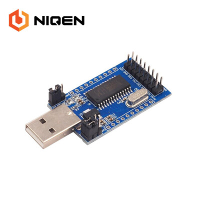
I bought a usb dongle to test with as my X9SRL as it has an internal USB-A jack on the board.
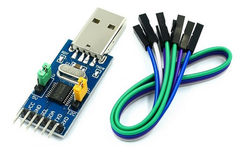
FT200XD is a USB to I2C interface with the following advanced features:

What do you use to drive an LCD on amd64?
 
FT200XD is an USB to I2C slave converter. I am still not 100 % sure, but from all what I understand about I2C, that means, you can connect this dongle as an I2C device to an existing I2C bus (which got already a master), and this won’t work with an AMD64 board, which got nothing I2C.
My best educated guess is that you need something like this one:

In the description about I2C is written in Chinenglish:
"Ø Only doMaster.20K,100K,400K,750KMore communication rate adjustable"

This sounds like an I2C master. Yet, remains the question of the driver.
 
I would use RS232 and a small Atmel controller to convert the stuff to I2C. This might add an FTDI USB-RS232 dongle but matches my actual skills :).
 
I decided to get a few more. See what works.


This should round out the collection.
 
I would use RS232 and a small Atmel controller to convert the stuff to I2C. This might add an FTDI USB-RS232 dongle but matches my actual skills :).
Here in Brazil, I found this one based on an ATtiny85:

This seems to do the USB to I2C/SPI conversion via an Atmel contoller. Is it really easy to address an Atmel? I neve did this, but would be ready to learn.
 
For the mere USB to serial conversion, FreeBSD got a CH341 driver as a kernel module - uchcom(4). For sure this module won't enable I2C/SPI, however, I can imagine that this would be a good basis to get I2C working as well.

The tiny CH341T conversion boards (the one that you found and the one that I found as well) feature a 12.000 MHz quartz. This means that we can get USB1 full speed = 12 Mbit/s out of it. For addressing the 16x2/20x4 displays this is way more than enough. This would even serve for high speed I2C operation (3.4 MHz) as well. I am looking for a device which would be able to address ADCs and DACs, like these ones:


From the specs, the USB to I2C converter based on the CH341T should work. I could need some help for the driver, though.
Anyway, I just ordered this one:
 
...
...
What do you use to drive an LCD on amd64?
There is yet another almost unknown option, namely the parallel port I2C bit-banging interface lpbb(4)

Even modern x86 motherboards feature parallel port headers, only these are no more connected to the outside. For example, I got an ASRock B250M Pro4, and I can see the LPT1 pinout on board:

ASRock-LPT1.jpg


With FreeBSD 13.0-RELEASE-p7, this is still activated:
dmesg
Code:
...
ppc1: <Parallel port> port 0x378-0x37f,0x778-0x77f irq 5 drq 3 on acpi0
ppc1: SMC-like chipset (ECP/EPP/PS2/NIBBLE) in COMPATIBLE mode
ppc1: FIFO with 16/16/9 bytes threshold
ppbus0: <Parallel port bus> on ppc1
lpt0: <Printer> on ppbus0
lpt0: Interrupt-driven port
ppi0: <Parallel I/O> on ppbus0
...

I can load the lpbb kernel module, and this enables an I2C bus in FreeBSD:

kldload lpbb.ko
kldstat
Code:
...
14    1 0xffffffff8232f000     2228 lpbb.ko
15    1 0xffffffff82332000     326c iicbb.ko
16    1 0xffffffff82336000     433c iicbus.ko

We only would need to produce the quite simple adapter circuit which is lined out on said man page.
 
That was kinda why I posted.
Hoping someone with SuperMicro server board is using an external interface.
The boards have a management system to talk to disk backplane.
I thought it was i2c. Shows as SES management in dmesg.

I have some hardware coming. I like USB approach as it is easily transferable.
I did see that tiny USB attiny version. Would have bought one but high shipping.

Had to revamp my order. I was worried about CH341 with no designator. Wanted CH341T.

Also got a GPIO expander by not reading well and researching. Bad listing.

 
The SMBus, which is present on most motherboards, is actually a subset of I2C, here from dmesg of my ASRock:
Code:
...
ichsmb0: <Intel Kaby Lake SMBus controller> port 0xf000-0xf01f mem 0xdf24a000-0xdf24a0ff irq 16 at device 31.4 on pci0
smbus0: <System Management Bus> on ichsmb0
...
With that the only problem is, that I don't see any SMBus pinout on the board, where I could connect something. Perhaps pin 5 (SMCLK = SCL) and Pin 6 (SMDAT = SDA) of an unused PCIe slot could be used:

There is yet another option, using the I2C interface of the video port, but it seems no to work in general:
 
Dear obsigna,
Is it really easy to address an Atmel? I neve did this, but would be ready to learn.
There are a few tools in the ports system. Please seek for AVR at freshports. In case of my experience I have used ATmega in the past. But I am not sure if I did the programming with Debian or FreeBSD. I have build the programmer based on a schematic diagram published within the AVRGCC project or so. The PC interface has been the LPT port. The programming has been done with devel/avrdude.
 
Sadly the SMBUS is usually internal to the mobo, so it is a no-go.

Another option would be to use a (secondary) graphics card.
Some graphics cards have their I2C port handler in their freedesktop xf86-driver-... source. Most of the drivers use the int86 VESA BIOS interface, though, so check before getting a graphics card for this purpose. If it is a microcontroller, one could (ab)use an unused VGA port for I2C.
(You know, the VESA line, for EDID, DPMS etc, it is an I2C line)
 
Sadly the SMBUS is usually internal to the mobo, so it is a no-go.
I am not that pessimistic about this option. FreeBSD comes with a smb(4) character device driver, which according to the man page:
... provides generic I/O to any smbus(4) instance. To control SMB devices, use /dev/smb? with the ioctls described below. Any of these ioctl commands takes a pointer to struct smbcmd as its argument. ...
We need to find pins where we can connect our I2C devices. I got an almost unused x86 machine with a free mini-PCIe slot. When I find some time (don't hold your breath), I will attach an I2C device which I know very very well (the ADS1115 - 16 bit ADC) to the pins 24 (VDD), 26 (GND), 30 (SCL), 32 (SDA) of it, and then I will see how far this goes.
 
While researching items in /dev I stumbled into this:
 
That looks very promising. However, I don't own this high precision soldering device, but fortunately, the PCIe connector gaps are not that tiny like that of the DIMM connectors. So, I need to go the PCIe path.

I found already out, that I needed to call kldload smb.ko in order to activate /dev/smb0. On FreeBSD, the SMBus is realized on top of the IIC bus, see smbus(4) and iicsmb(4).

Reading that article, I am quit optimistic now. And we learn as well that the rainy weather in the UK and the closed pubs because of COVID19 are good for something:)

That said, everybody take care, stay healthy and write useful articles!
 
My SuperMicro X9SRL motherboard has i2c. The manual has this:
The Power Supply I2C Connector, located at
JPI2C1, monitors the status of the power sup-
ply, fan and system temperature. See the table
on the right for pin definitions.
It does not look like the standard pinout of SDA SCL CLK + -

This also looks relevant:
System Management Bus (JIPMB)
A System Management Bus header for the
IPMI slot is located at IPMB. Connect the
appropriate cable here to use the IPMB I2C
connection on your system.
 
Are you talking about this one?
Bildschirmfoto 2022-02-27 um 22.44.48.png

This would be easy: 1 = SCL, 2 = SDA, 4 = GND, 5 = VDD (3.3 V). Note, for your display, 3.3 V is not sufficient, it needs 5 V. So, you would connect only SCL and SDA of the display to pins 1 and 2 respectively, and take 5 V and GND directly from free red and black wires out of the PSU.
 
Wow reading the manual. What a concept.
I believe these are the SES0 device I see in dmesg:
T-SGPIO & SCU-SGPIO Headers
Two T-SGPIO (Serial-Link General Purpose
Input/Output) headers are supported on the
motherboard. Additionally, one SCU-SGPIO
port (for SCU) is also located next to USB 8/9.
These headers are used to communicate with
the enclosure management chip in the system.
See the table on the right for pin definitions.
Refer to the board layout below for the loca-
tions of the headers.

But right underneath this is the section on TPM chip/socket.
Are'nt those i2c as well? Maybe it was SPI...
 
Wow reading the manual. What a concept.
I believe these are the SES0 device I see in dmesg:


But right underneath this is the section on TPM chip/socket.
Are'nt those i2c as well? Maybe it was SPI...
I don't believe this is I2C, it may be SPI.

I forgot to say, that JPI2C1 is not 100 % I2C but it is actually SMB. Most probably you need some glue code for addressing your I2C devices. Does FreeBSD on this SuperMicro board already come up with /dev/smbX device identifiers? In case not, what happens, if you issue kldload smb.ko on the command line?

Another hurdle is, that we cannot say now, whether this connector belongs to the regular SMBus of the system, which got already a bus master, or whether this is meant to be connected as a client to a 3rd party SMBus wich got its own bus master. In the second case this connector would be useless for using it with your display.
 
smb.ko is being loaded automatically. I have smb0 and devices (could be RAM)
Code:
root@x9srl:/home/firewall # smbmsg -p
Probing for devices on /dev/smb0:
Device @0x10: rw
Device @0x5a: rw
Device @0x88: rw
Device @0x90: rw
Device @0xd2: rw
Device @0xdc: rw

I have hand loaded iic.ko with no device nodes showing there.
 
OK, now connect the display to JPI2C1 -- important, VDD must be 5 V. Then look whether it is enumerated by smbmsg -p.

Perhaps on /dev/smb1?
 
I need to regroup and use another SuperMicro board for experimenting. The X9SRL is my firewall.
Thank You so much for the help.
 
whether this connector belongs to the regular SMBus of the system, which got already a bus master, or whether this is meant to be connected as a client to a 3rd party SMBus wich got its own bus master. In the second case this connector would be useless for using it with your display.
Yes I was wondering about this too. It appears that the IPMI/BMC is the master and monitors the board via SMBus.
That was for an older SuperMicro board with external IPMI PCI module.
I don't know if true on my integrated BMC. From my reading of the BMC GUI I would say probably so.

I want to prototype this concept on another rig first. I have X10SRL which should be similar.
Currently covered on my bench by embedded boards.
Alot of SuperMicro server boards have these power supply i2C connectors.
Even X8 boards had them if i remember right. Tyan server boards have them too.
 
Last weekend, I ordered the open collector hex inverter chip 74LS05, which I would need to turn the internal parallel port into I2C by using the FreeBSD's bit banging driver - lpbb(4). Here in Brazil we have carneval and I will receive it only on Thursday. In advance, I just started to draw the scheme of the tiny adapter board using KiCAD, and I was looking up the pinout of the parallel port male connector on the main board. I found it here:

However, I found more on this page. Here the parallel port is used to directly connect the HD44780 display without the PCF8574 I2C/GPIO converter in the middle. So, if you are only looking for means to connect the display, this would be the straightest option.

Anyway, my aim is still to connect I2C devices, and I will explore the lpbb facility once the 74LS05 arrived.
 
I reworked the scheme in lpbb(4) and created a PCB layout using KiCAD. Bear with me, I am a chemist and not an electronics professional. I allow anybody to lough at me, as long as you give constructive advises on how to improve the design.

Presumably, tomorrow the 74LS05 chips will arrive and I will reproduce the design on a prototype board first. In case it works well, then I will make the KiCAD project available on GitHub. If anybody considers a mass production, I suggest to refactor this for using SMD parts.
Bildschirmfoto 2022-03-02 um 10.41.09.png

Bildschirmfoto 2022-03-02 um 10.41.44.png
Bildschirmfoto 2022-03-02 um 10.43.17.png


The tiny board is meant to be plugged in vertically in to the parallel port's 25 pin header on the motherboard, for example this one:
ASRock-LPT1.jpg
 
Use a logic level converter to convert the 3.3V signals to 5V TTL and vise versa. You could drive a 5V TTL input with a 3.3V output (3.3V is above the logic '1' minimal voltage of TTL) but driving a 3.3V input with a 5V TTL signal is likely going to blow something up (unless the chip is 5V tolerant but I doubt that).

The TXS0108E is useful. You can buy these on breakout boards. They're not that expensive.


Back
Top